seat Workshop Repair Guides

SEAT Workshop Service and Repair Manuals

Engine control unit > < Checking additional signals
Motronic injection and ignition system (1.8 l engine)
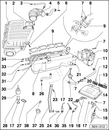
Servicing injection system
Removing and installing parts of the injection system
 
N24-1212
  • Air cleaner
    • ◆ Dismantling and assembling
  • Air mass meter (G70)*
    • ◆ Checking => Page 24-33
    • ◆ 5 pin connector
  • To activated charcoal filter solenoid valve 1 (N80)*/** or charge pressure control solenoid valve (N75)*/**
    • ◆ Activated charcoal filter system

=> Repair group 20; Activated charcoal filter system

  • Intake hose

=> Repair group 21; Charge air system with turbocharger; Removing and installing parts of charge air cooling

  • To crankcase breather
  • To secondary air pump

=> Repair group 26; Secondary air system

 
N24-1212
  • 10 Nm
  • Intake manifold
  • Gasket
    • ◆ Renew
  • Throttle valve control part (J338)*
    • ◆ Checking => Page 24-38
    • When renewing:
    • ◆ Match engine control unit => Page 24-111
    • Vehicles with an automatic gearbox:
    • ◆ Match gearbox control unit:

=> Automatic gearbox 09B self-diagnosis; Repair group 01; Performing self-diagnosis; Initiating basic settings

  • Connecting hose
    • ◆ Between throttle valve control part and connection on fuel rail
      => Page 24-18, item 12
 
N24-1212
  • 40-pin connector
    • ◆ Only disconnect or connect with ignition switched off
    • ◆ Release to disconnect
  • 81-pin connector
    • ◆ Only disconnect or connect with ignition switched off
    • ◆ Release to disconnect
  • Engine control unit*
    • (Motronic control unit -J220)
    • ◆ Fitting location: behind battery
    • ◆ Checking voltage supply => Page 24-103
    • ◆ Procedure after voltage supply open circuit => Page 24-107
    • ◆ Renew => Page 24-109
  • Engine speed sender (G28)*
    • ◆ Inductive sender
    • ◆ Checking => Page 24-58
 
N24-1212
  • 3 pin connector
    • ◆ Grey
    • ◆ For engine speed sender
    • ◆ Fitting location => Page 24-1, engine compartment overview
  • O-ring
    • ◆ Renew if damaged
  • 4 pin connector
    • ◆ Black for Lambda probe 2 after catalyst (G130) and Lambda probe heater (Z19)
    • ◆ On underside of vehicle
  • Lambda probe 2 after catalyst (G130)*, 50 Nm
    • ◆ Location: Behind catalyst
    • ◆ Grease only the threads with "G 052 112 A3"; "G 052 112 A3" must not get into the slots on the probe body
    • ◆ Checking Lambda probe and Lambda regulation after catalyst => Page 24-88
    • ◆ Checking Lambda probe heating for Lambda probe after catalyst => Page 24-28
 
N24-1212
  • Non-return valve
  • To brake servo vacuum pipe
  • Intake air temperature sender (G42)*
    • ◆ Checking => Page 24-51
  • 20 Nm
  • 25 Nm
  • Support
    • ◆ Between intake manifold and engine block
  • To crankcase breather
  • Retaining clip
    • ◆ Check seated securely
 
N24-1212
  • Coolant temperature sender (G62)*
    • ◆ For engine control unit
    • ◆ Checking
    • ◆ If necessary release pressure in cooling system before removing
  • Connector
    • ◆ Black, 2-pin
    • ◆ For coolant temperature sender (G62)
  • Fuel rail with injectors
    • ◆ Dismantling and assembling => Page 24-17
  • Vacuum connection
    • ◆ To overrun cut-off valve

=> Repair group 21; Checking charge pressure system; Overview of turbocharger

 
N24-1212
  • Supply pipe/hose
    • ◆ Secure with spring-type clips
    • ◆ Check securely seated
    • ◆ From fuel filter:

=> Repair Group 20; Removing and installing parts of fuel supply system; Removing and installing fuel tank with attachments and fuel filter

  • Return pipe
    • ◆ Secure with spring-type clips
    • ◆ Check securely seated
    • ◆ To the fuel delivery unit in fuel tank

=> Repair Group 20; Removing and installing parts of fuel supply system; Removing and installing fuel tank with attachments and fuel filter

  • From activated charcoal filter solenoid valve 1 (N80)
    • ◆ Activated charcoal filter system

=> Repair group 20; Activated charcoal filter system

 
N24-1212
  • 6-pin connector
    • ◆ Black for Lambda probe 1 before catalyst (G39) and Lambda probe heater (Z19)
    • ◆ On underside of vehicle
  • Lambda probe 1 before catalyst (G39)*, 50Nm
    • ◆ Fitting location: catalyst
    • ◆ Grease only the threads with "G 052 112 A3"; "G 052 112 A3" must not get into the slots on the probe body
    • ◆ Checking Lambda control before catalyst
      => Page 24-83
    • ◆ Checking Lambda probe heating => Page 24-23
  • Charge pressure sender (G31)*
  • 6 Nm

Engine control unit > < Checking additional signals