seat Workshop Repair Guides

SEAT Workshop Service and Repair Manuals

Checking signal from/to air conditioning system > < Checking additional signals
Motronic injection and ignition system (4-Cyl.)
Checking additional signals
Checking speed signal

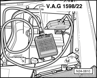
Special tools, workshop equipment, testers, measuring instruments and auxiliary items required

  • ◆ Fault reader V.A.G 1551 or vehicle system tester V.A.G 1552 with cable V.A.G 1551/3
  • ◆ Test box V.A.G 1598/22
  • ◆ Hand multimeter V.A.G 1526 or multimeter V.A.G 1715
  • ◆ Adapter set V.A.G 1594
  • ◆ Current flow diagram

Check conditions

  • ● The battery voltage must be at least 11.5 V.
  • ● Speedometer must be OK., checking speedometer:

=> Electrical system; Repair group 90

Test sequence

Note:

To check the speed signal the vehicle must be driven. To do this a second person is necessary.

Warning!
Secure fault reader to rear seat and operate from this position.
  • ‒ Connect fault reader V.A.G 1551 (V.A.G 1552). Start engine and select "Address word" 01 of engine control unit. When doing this the engine must be running at idling speed.
    (Connecting fault reader and selecting engine control unit .)
 
→ Indicated on display:
Rapid data transfer    HELP
Select function XX
  • ‒ Press keys 0 and 8 for the function "Read measured value block" and confirm entry with Q key.
 
→ Indicated on display:
Read measured value block    HELP
Input display group number XXX
  • ‒ Press keys 0, 1 and 1 for "Display group number 11" and confirm entry with Q key.
 
→ Indicated on display:
(1...4 = Display zones)
Read measured value block    11    ⇒
    1    2    3    4
  • ‒ Carry out test drive with a 2nd person to observe display.
  • ‒ Observe figure displayed in display zone 3:
        Specification: approx. driven speed
  • ‒ Press the ⇒key.
  • ‒ Press keys 0 and 6 for the "End output" function and confirm input with the Q key.
  • ‒ Switch off ignition.

If no speed is indicated:

 
N24-0810
  • ‒ → Connect test box V.A.G 1598/22 to control unit wiring harness.
  • ‒ Connect multimeter to measure voltage between test box sockets 2+20.
  • ‒ Switch on ignition.
  • ‒ Lift vehicle at front left.
  • ‒ Rotate front wheel and observe voltage display.
        Specification: between 0 and at least 4 Volt fluctuating

If the display does not fluctuate:

  • ‒ Check wiring to speedometer/speedometer sender.

=> Current flow diagrams, Electrical fault finding and Fitting locations binder

Checking signal from/to air conditioning system > < Checking additional signals