seat Workshop Repair Guides

SEAT Workshop Service and Repair Manuals

Checking ignition coils with output stage > < Test data, spark plugs
Motronic injection and ignition system (6-cylinder engine)
Servicing ignition system
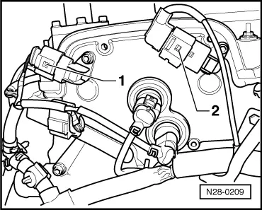
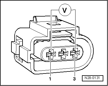
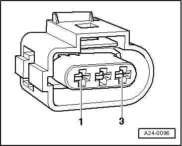
Checking Hall sender

Notes:

  • ◆ Always mark connectors before pulling off (danger of interchanging).
  • ◆ Only gold plated connectors may be used to service contacts in connectors for Hall senders.

Special tools, workshop equipment, testers, measuring instruments and auxiliary items required

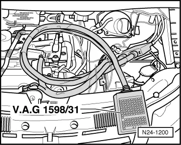
  • ◆ Test box V.A.G 1598/31
  • ◆ Hand multimeter V.A.G 1526 or multimeter V.A.G 1715
  • ◆ Adapter set V.A.G 1594
  • ◆ Current flow diagram

Check conditions

  • ● Hall sender screwed on tight
  • ● The battery voltage must be at least 11.5 V.
 
N28-0209

Test sequence

  • ‒ → Pull 3-pin connector off Hall sender (G40) -1-.

 
N28-0131
  • ‒ → Connect multimeter to measure voltage with adapter cables from V.A.G 1594 to contacts 1 (positive) and 3 (earth) on the Hall sender connector.
  • ‒ Switch on ignition.
        Specification: min. 4.5 V
  • ‒ Switch off ignition.

If no voltage is present:

 
N24-1200
  • ‒ Remove battery.
  • ‒ → Connect test box V.A.G 1598/31 to control unit wiring harness. The engine control unit remains disconnected.

 
A24-0096
  • ‒ → Check wiring for open circuit between test box and connector using current flow diagram.
        Contact 1+socket 98
        Contact 2+socket 86
        Contact 3+socket 108
        Wire resistance: Max. 1.5 ω
  • ‒ Additionally check wires for short to one another.
        Specification: ∞ω

If no wiring fault is detected and voltage was present between contacts 1+3:

  • ‒ Renew Hall sender (G40)
  • ‒ Interrogate fault memory, if necessary, repair any faults and then erase fault memory , interrogating and erasing fault memory.
 
N28-0209
  • ‒ Read-out the readiness code=> Page 01-64.

Test sequence for Hall sender G163 (exhaust camshaft)

  • ‒ → Pull 3-pin connector off Hall sender (G163) -2-.

 
N28-0131
  • ‒ → Connect multimeter to measure voltage with adapter cables from V.A.G 1594 to contacts 1 (positive) and 3 (earth) on the Hall sender connector.
  • ‒ Switch on ignition.
        Specification: min. 4.5 V
  • ‒ Switch off ignition.

If no voltage is present:

 
N24-1200
  • ‒ Remove battery.
  • ‒ → Connect test box V.A.G 1598/31 to control unit wiring harness. The engine control unit remains disconnected.

 
A24-0096
  • ‒ → Check wiring for open circuit between test box and connector using current flow diagram.
        Contact 1+socket 98
        Contact 2+socket 87
        Contact 3+socket 108
        Wire resistance: max. 1.5 ω
  • ‒ Additionally check wires for short to one another.
        Specification: ∞ω

If no wiring fault is detected and voltage was present between contacts 1+3:

  • ‒ Renew Hall sender (G163).
  • ‒ Interrogate fault memory, if necessary, repair any faults and then erase fault memory => Page 01-16, interrogating and erasing fault memory.
  • ‒ Read-out the readiness code=> Page 01-64.

If no wiring fault is detected and no voltage was present between contacts 1+3:

  • ‒ Replace engine control unit
    => Page 24-150.

Checking ignition coils with output stage > < Test data, spark plugs