seat Workshop Repair Guides

SEAT Workshop Service and Repair Manuals

Checking knock sensor > < Checking Hall sender
Motronic injection and ignition system (6-cylinder engine)
Servicing ignition system
Checking ignition coils with output stage

Special tools, workshop equipment, testers, measuring instruments and auxiliary items required

  • ◆ Test box V.A.G 1598/31
  • ◆ Hand multimeter V.A.G 1526 or multimeter V.A.G 1715
  • ◆ Diode test lamp V.A.G 1527
  • ◆ Adapter set V.A.G 1594
  • ◆ Current flow diagram

Check conditions

 
N01-0485
  • ‒ → Pull fuse No. 14 out of fuse holder.

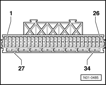
Note:

Removing fuse No. 14 interrupts the voltage supply to the injectors and fuel pump.

  • ● All fuses must be OK.
  • ● Engine speed sender OK, checking
  • ● Hall sender OK, checking

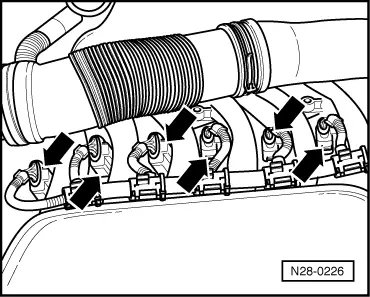
Note:

Ignition coils and output stages are single components and cannot be renewed separately.

 
N28-0226

Test sequence

  • ‒ → Pull connector off ignition coil to be checked.

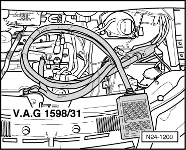
Checking voltage supply

 
A24-0094
  • ‒ → Measure supply voltage between contacts 1 + 3 and 2 + 3 of the pulled-off connector using multimeter and adapters from V.A.G 1594.
  • ‒ Switch on ignition.
        Specification: min. 11.5 V
  • ‒ Switch off ignition.

If no voltage is present:

 
A24-0094
  • ‒ → Check wiring for open circuit between contact 3 of 4-pin connector and relay plate using current flow diagram.
        Wire resistance: max. 1.5 ω
  • ‒ Check wiring for open circuit between contact 1 of 4-pin connector to earth and contact 2 to earth.
        Wire resistance: max. 1.5 ω

If there is no fault in the supply voltage:

Checking activation

 
A24-0094
  • ‒ → Using adapters from V.A.G 1594, connect diode test lamp V.A.G 1527 to
        Contact 4 and engine earth
    of the connector pulled off cylinder 1.
  • ‒ Operate starter and check the ignition signal from engine control unit.
        The LED must flicker
  • ‒ Repeat test on connectors for cylinders 2 through 6.
  • ‒ Switch off ignition.

When the LED flickers and the supply voltage is OK.:

  • ‒ Renew respective ignition coil with output stage.
  • ‒ Interrogate fault memory, if necessary, repair any faults and then erase fault memory , interrogating and erasing fault memory.
  • ‒ Read-out the readiness code=> Page 01-64.

The LED does not flicker:

Checking wiring

  • ‒ Remove battery.
 
N24-1200
  • ‒ → Connect test box V.A.G 1598/31 to control unit wiring harness. The engine control unit remains disconnected.

 
A24-0094
  • ‒ → Check wiring for open circuit between test box and 4-pin connector using current flow diagram. For
        Cylinder 1, contact 4 + socket 102
        Cylinder 2, contact 4 + socket 110
        Cylinder 3, contact 4 + socket 94
        Cylinder 4, contact 4 + socket 111
        Cylinder 5, contact 4 + socket 103
        Cylinder 6, contact 4 + socket 95
        Wire resistance: max. 1.5 ω
  • ‒ Additionally check wires for short to one another.
        Specification: ∞ω

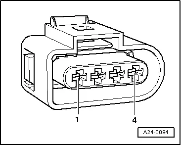
If no wiring fault is detected and voltage was present between contacts 1+3 and 2+3.

  • ‒ Replace engine control unit
    => Page 24-150.

Checking knock sensor > < Checking Hall sender