
Leon Mk1
| → Indicated on display: |
|
||
|
| → Indicated on display: |
|
||
|
| → Indicated on display: (1...4 = Display zones) |
|
||||||||||||||||||||||||||||||||||||||||
|
Note: Checking the knock sensors must be performed during a test drive because the diagnosis of the knock sensors is not activated until the engine speed exceeds 2000 rpm and the engine is loaded by more than 40 %.
Observe the valid safety precautions when carrying out a test drive => Page 28-8.
If the specification is attained:
Continuation: If the specifications are not obtained:
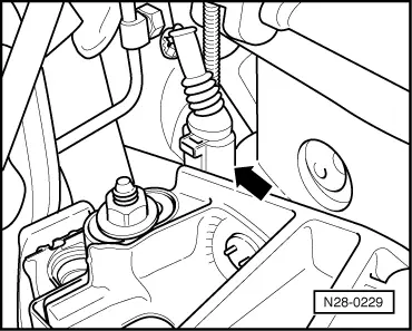
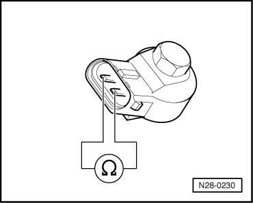
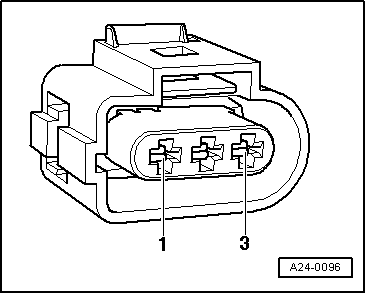
Checking resistance of knock sensors Knock sensor 1 (G61) | |||||||||||||||||||||||||||||||||||||||||
 |
|
|
 |
|
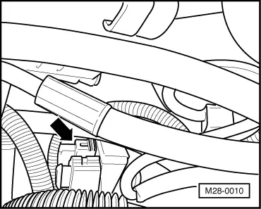
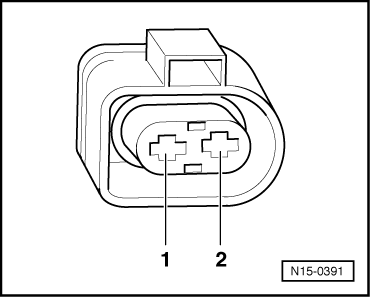
Knock sensor 2 (G66) |
 |
|
|
 |
|
If the specification is not obtained:
If the specification is obtained: Checking wiring
|
 |
|
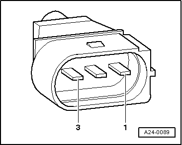
Knock sensor 1 (G61) |
 |
|
Knock sensor 2 (G66) |
 |
|
If no wiring fault is detected:
If the fault is still present: |