seat Workshop Repair Guides

SEAT Workshop Service and Repair Manuals

Repair work on refrigerant circuit which may only be carried out in suitable workshops by specially trained mechanics, vehicles > < Components of the automatic air conditioning system (Climatronic) in the passenger compartment
Checking cut-in signal for air conditioner compressor regulating valveN280
Checking cut-in signal for air conditioner compressor regulating valve -N280-
Special tools and workshop equipment required
t  Auxiliary cable kit -V.A.G 1594 C-
t  Vehicle diagnostic, testing and information system -VAS 5051 A- with sensor head -VAS 5051/8-
  Note
The following describes the procedure for checking a „Denso“ air conditioner compressor (type „7 SEU 16“). Perform the check in the same manner on vehicles with a different type of compressor or a compressor from a different manufacturer.
–  Switch off ignition.
–  Remove the upper engine protection element (e.g. on vehicles, for the access of the connector is reached from above) → Engine, mechanics; Rep. gr.13.
–  Remove the noise insulation ((e.g. on vehicles, where the access of the connector is not reached from above). → General body repairs, exterior; Rep. gr.66
   
–  Remove the electrical connector that leads to the air conditioner compressor regulating valve -N280- at plug connector -1-.
  A10-1637
–  Use adapter cable from auxiliary measuring set -V.A.G 1594 C- to re-connect connector -A- and connector -B- at regulating valve.
  Note
t  On vehicles with automatically controlled air conditioner, the operating and display unit, Climatronic control unit -J255- actuates the air conditioner compressor by way of the air conditioner compressor regulating valve -N280-.
t  On vehicles with manually controlled air conditioner, the air conditioning system control unit -J301- actuates the air conditioner compressor by way of -N280-.
t  In the measured value block of the respective air conditioning unit controller, the controlling of the -N280- and the current that flows through the -N280- is indicated - value measured by the operating and display unit (Climatronic control unit -J255-) - or by the Air conditioning control unit -J301- → "Guided fault-finding" function of vehicle diagnostic, testing and information system VAS 505X.
  A87-0390
t  You can also use an improvised adapter lead for this test. For this, use one connector -A- and -B- each (with part number 1J0 973 702 and 1J0 973 802 and the corresponding plug contacts → Electronic parts catalogue), two commercially available sockets for banana plugs -C- and two wires with a cross section of 0.5 mm2 for example.
  A87-0389
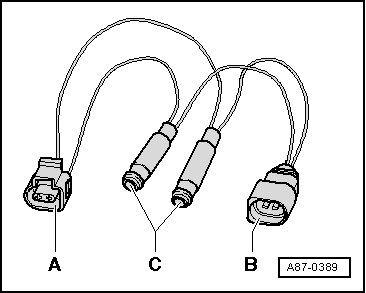
–  Connect sensor head -VAS 5051/8- to adapter cables.
–  Test lead (signal wire) to contact -2- of connector -A-
–  Test lead (screen, earth) to contact -1- of connector -A-
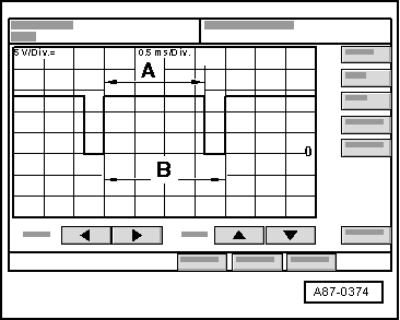
–  On the vehicle diagnostic, testing and information system -VAS 505X-, set Measurement mode: DSO (Digital Storage Oscilloscope) and select the setting 5V/div DC = 0.5 ms/div (5 V DC and 0.5 milliseconds per unit)
–  Start the engine.
–  On operating and display unit (Climatronic control unit -J255-), select „Lo“ temperature setting for driver's and front passenger's side (vehicles with automatic air conditioner).
–  Turn rotary temperature setting control on air conditioner control panel (air conditioning system control unit -J301-) anti-clockwise as far as „cold“ stop (vehicles with manually controlled air conditioner).
–  On the operating and display unit (Climatronic control unit -J255-), press the buttons AUTO and ON/OFF / ECON or AC to activate/deactivate the air conditioner compressor regulating valve -N280- (on vehicles with automatic air conditioner).
  Note
Depending on the version of the operating and display unit, the operating mode „ECON“ is active when, on the version with an ECON button, the indicator lamp in the button is illuminated, and on the version with an AC button, the indicator lamp is not illuminated.
–  On the air conditioner controls (air conditioning system control unit -J301-), press the button AC to activate and deactivate actuation of the air conditioner compressor regulating valve -N280- (vehicles with manually controlled air conditioner).
Depending on the setting of the operating and display unit (Climatronic control unit -J255-), the display of the oscilloscope will show:
–  In „OFF“ or „ECON“ mode („AC off“): No square-wave signal (regulating valve is not activated)
  A87-0390
–  In „AUTO“ mode (with „AC“ switched on) and „Lo“ temperature setting (rotary temperature control on „cold“ stop): Square-wave signal with pulse width -A- between 75 % and 100 % (regulating valve is actuated)
  Note
t  The figure shows a signal with a duty cycle of approx. 80 %.
t  The amplitude of the pulse -A- depends on the desired cooling power, the on-board voltage, etc. (in the field -A-, the flow is controlled via air conditioning system compressor regulating valve -N280- from the Climatronic control unit -J255-/) or air conditioning control unit -J301-.
t  The signal distance -B- is always 2 milliseconds (corresponding to a frequency of 500 Hertz).
  A87-0374
t  The duty cycle is derived from the ratio of pulse width -A- to signal distance -B-.
–  The setting on the operating and display unit, Climatronic control unit -J255- or on the air conditioning system control unit -J301- and the measured ambient influences govern the pulse width of the square-wave signal (signal ratio between 100 % and greater than 30 %, the regulating valve is actuated such that the compressor output required to obtain the specified temperatures is achieved).
  Note
t  In „Auto“ mode with „Lo“ temperature setting („AC“ switched on, rotary temperature control on „cold“ stop with manually controlled air conditioner), the air conditioning system compressor regulating valve -N280- is actuated such that the maximum permissible current of approx. 0.65 A flows via the -N280- (maximum compressor output).
t  During regular operation, the controlling period depends on the required cooling output, the voltage of the vehicle, etc. The controlling continues until an average current intensity of approx. 0.3 A flows.
  A87-0374

Repair work on refrigerant circuit which may only be carried out in suitable workshops by specially trained mechanics, vehicles > < Components of the automatic air conditioning system (Climatronic) in the passenger compartment