seat Workshop Repair Guides

SEAT Workshop Service and Repair Manuals

Checking gearbox oil > < Adjusting gear selector mechanism
5-speed manual gearbox 006
Removing and installing gearbox
Removing and installing gearbox - Vehicles with 4 cylinder engine -
 
N37-0095

Removing

  • ‒ → With the vehicle resting on its wheels loosen left-hand wheel hub/drive shaft bolt and left and right-hand wheel securing bolts.

Note:

Note radio coding for vehicles with coded radio.

 
N34-0278
  • ‒ With the ignition switched off disconnect the battery earth strap (in engine compartment and if fitted, under driver's side).

=> Electrical system; Repair group 27

Vehicles with Diesel engine

  • ‒ → Remove upper section of charge air pipe (arrow)
 
N34-0279
  • ‒ → Remove upper engine cover (arrow)

 
N34-0259
  • ‒ Remove air cleaner.
  • ‒ → Lever gear selector cable -A- off gear selector lever.
  • ‒ Lever gate selector cable -B- off relay lever.
 
N34-0264
  • ‒ → Pull both cables out from retainer on gearbox, to do this press clips together (arrows).

 
N30-0112
  • ‒ → Lever clip for pipe work out from slave cylinder (direction of arrow), pull pipe out and seal with 10 mm plug.
  • ‒ Pull pipe work out of retainer on gearbox.
 
N34-0275
  • ‒ → Pull off reverse light connector (arrow). Disconnect all other electrical connections and earth wires from gearbox and from the engine/gearbox securing bolts.
  • ‒ Remove engine/gearbox upper securing bolts.

 
N34-0268
  • ‒ → Remove right-hand engine mounting nuts
 
N34-0273
  • ‒ → Fit support bar 10-222A together with legs 10-222 A/5.

 
N34-0276
  • ‒ → Fit support bar 10-222 A/5 with body bolts (arrows).
  • ‒ Take weight of engine/gearbox assembly on the spindles.
 
N34-0272
  • ‒ Remove insulation tray below engine/gearbox, if fitted.
  • ‒ Remove starter.

=> Repair group 27; Removing and installing starter.

 
N34-0280

Vehicles with Diesel engine

  • ‒ → Remove charge air pipe from charge air cooler (arrow)
  • ‒ Remove both wheels

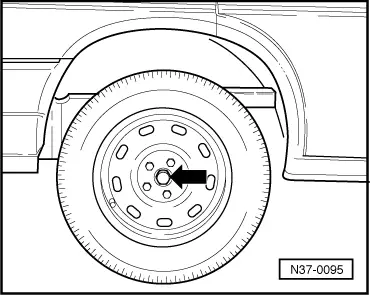
Remove/loosen left and right-hand wheel mountings as follows:

 
N40-0126
  • ‒ → Press track rod off steering arm.
  •     1 -    Hooks (commercially available) e.g. Kukko No. 1-90
  •     2 -    Puller (commercially available) e.g. Kukko No. 20-10
  • ‒ Tie up track rod

 
N40-0118
  • ‒ → Separate left and right-hand wheel bearing housing/lower ball joint bolted connection.
 
N40-0110
  • ‒ → Remove left and right-hand coupling link -1- on shock absorber.
  • ‒ Detach brake hose and, if fitted, ABS sensor cable from retainers on shock absorber.

 
N34-0270
  • ‒ Place drip tray underneath.
  • ‒ → Lever left-hand drive shaft out from gearbox and pull out from wheel hub.
 
N34-0686
  • ‒ → Insert sealing cap 3394 into gearbox.

 
N34-0269
  • ‒ Pull right-hand drive shaft out of centre bearing by tugging outwards on wheel mounting.
  • ‒ Tie-up drive shaft as high as possible. Do not damage paint on drive shaft.

Vehicles up to January 97

  • ‒ → Unbolt centre bearing from mounting on engine block (arrows) and pull with axle shaft out of gearbox or lever out if necessary.
  • ‒ Insert sealing cap 3394 into gearbox.

Vehicles from January 97

 
N34-0684
  • ‒ → Unbolt axle shaft bearing (arrows) and pull axle shaft out of gearbox.

 
N34-0685
  • ‒ → Remove engine/gearbox support -arrows 1 to 3-.
  • ‒ Insert sealing cap 3394 into gearbox.

Continuation for all vehicles

 
N10-0039
  • ‒ → Remove pendulum support -1-, to do this remove bolt and nuts -A-.

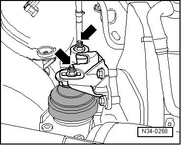
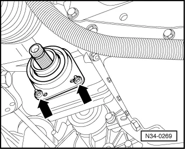
Note:

The pendulum support can be secured to the subframe with one bolt.

 
N34-0271
  • ‒ → Pull connector off road speed sender (arrow).
  • ‒ Remove flywheel cover plate.
 
N34-0281
  • ‒ → Separate gearbox mounting, to do this remove bolts -A- and -B-.
  • ‒ Push engine/gearbox assembly as far as possible to right.
  • ‒ Tilt engine/gearbox assembly, to do this raise right-hand spindle and lower left-hand spindle.

 
N34-0282
  • ‒ → Remove mounting from gearbox console (arrows).
 
N34-0296
  • ‒ Assemble gearbox jack with gearbox support 3282, adjustment plate 3282/21 for "006", gearbox and support elements as follows:
  • ‒ Place adjustment plate 3282/21 on gearbox support 3282. (Adjustment plate only fits in one position).
  • ‒ Align arms of gearbox support according to holes in adjustment plate.
  • ‒ → Bolt on support elements -A-, as illustrated, on adjustment plate.

 
N34-0277
  • ‒ → Place gearbox jack under vehicle, arrow symbol -B- (=> Illustration V34-0296) on adjustment plate points to front of vehicle.
  • ‒ Align adjustment plate parallel to gearbox and secure with a bolt.
  • ‒ Remove lower engine/gearbox securing bolts.
  • ‒ Press gearbox off dowels and lower carefully.
  • ‒ Change position of gearbox in the area of assembly carrier and body on left-hand side by lowering via the gearbox jack spindle.
 
N34-0267

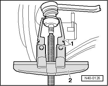
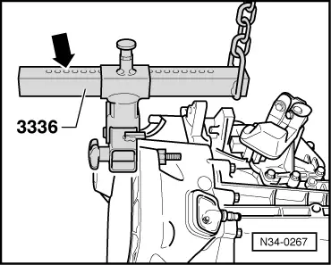
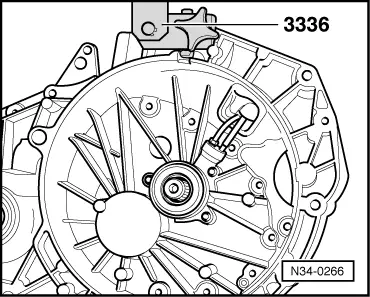
Transporting the gearbox

Special tool 3336 may be used to transport the gearbox and also when setting up gearbox mount 3282.

  • ‒ → Bolt gearbox lifting device 3336 to clutch housing.

 
N34-0266
  • ‒ → Set support beam on sliding piece with locking pin (arrow).

No. of holes visible = 7

  • ‒ Take gearbox out with workshop crane and gearbox lifting device 3336.

Installing

  • ‒ Clean input shaft splines and lightly grease with G000 100 grease.

The clutch plate must be able to slide lightly to and fro on the input shaft.
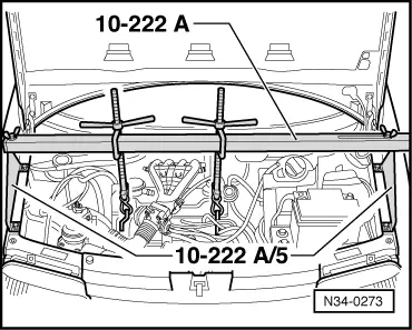
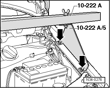
  • ‒ Check whether dowel sleeves for aligning engine/gearbox are fitted in cylinder block, install if necessary.
  • ‒ Ensure that the intermediate plate is correctly positioned on engine.
  • ‒ Assemble gearbox jack with gearbox support 3282, adjustment plate 3282/21 for "006" gearbox and support elements as follows:
 
N34-0296
  • ‒ Place adjustment plate 3282/21 on gearbox support 3282. (Adjustment plate only fits in one position).
  • ‒ Align arms of gearbox support according to holes in adjustment plate.
  • ‒ → Bolt on support elements -A-, as illustrated, on adjustment plate.
  • ‒ Place gearbox on gearbox jack.
  • ‒ Align adjustment plate and gearbox parallel with one another and secured with a bolt.
 
N34-0277
  • ‒ → Place gearbox jack under vehicle, arrow symbol -B- (=> Illustration N34-0296 on previous page) on adjustment plate points to front of vehicle.
  • ‒ Insert gearbox.
  • ‒ Install lower engine/gearbox securing bolts and bolts for starter when doing this insert starter.

 
N34-0282
  • ‒ → Install mounting on gearbox console (arrow).
 
N34-0281
  • ‒ Align engine/gearbox in installation position.
  • ‒ → Assemble gearbox mounting, to do this screw in bolts -A- and -B-.
  • ‒ Remove support bar 10-222A.
Warning!
Do not remove support bar 10-222A until the bolts securing the left-hand gearbox mounting have been tightened to torque setting.

 
N10-0039

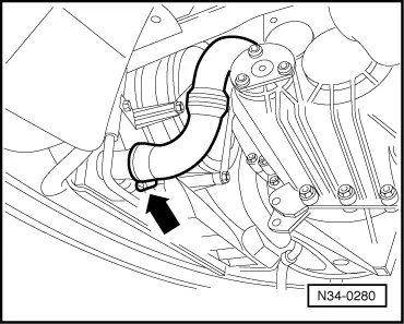
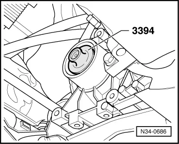
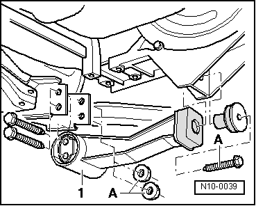
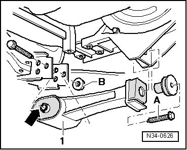
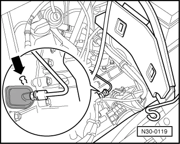
→ Pendulum support to gearbox

For start of production a steel pendulum support was produced with two bushes for mounting to subframe - Length of bushes = 90 mm.

 
N34-0626

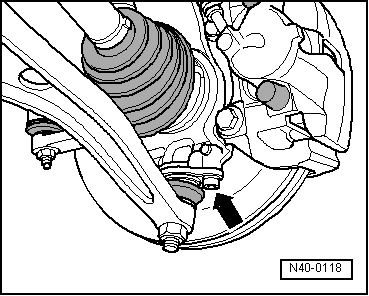
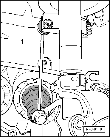
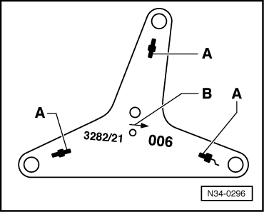
After a short run-up period the support will be substituted for an aluminium support -1- with one bush (arrow) - Length of bush = 90 mm.

Due to modifications to pendulum support mounting a shorter bush has been introduced - Length of bush = 85 mm.

  • ‒ Allocate pendulum support to subframe mounting:

Width of mounting

Identification

Length of bush(es) (arrow) in pendulum support

Number of bushes (arrow) in pendulum support

90 mm

3 holes

90 mm

11) or 2

85 mm

1 hole

85 mm

1

  • ‒ 1)Secure pendulum support with one bush into front subframe drilling.

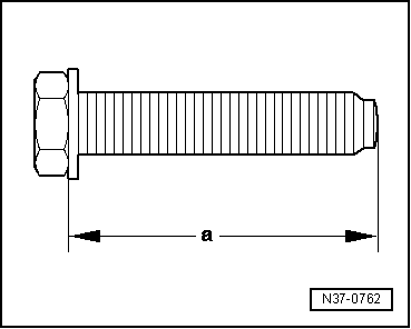
From 09.03.98 a longer bolt -A- has been introduced. The drilling in the pendulum support has been adapted to the longer bolt.

 
N37-0762

→ Allocation

Dimension -a-

Tightening torque

New:

88 mm

Tighten to 60 Nm + turn
90°further
- Always renew bolt

Previously:

78 mm

70 Nm

The new bolt cannot be installed in the old pendulum support.

If the pendulum support is renewed, the new bolt -A- must be installed.

 
N34-0271
  • ‒ → Reconnect road speed sender connector (arrow).
  • ‒ Install flywheel cover plate.
  • ‒ Install starter completely.

=> Repair group 27; Removing and installing starter.

 
N30-0120
  • ‒ Take sealing caps 3394 out from shaft openings.
  • ‒ → The securing ring -A- must be replaced before installing left-hand shaft.
  • ‒ Push left-hand shaft in (direction of arrow), carefully drive in with synthetic head hammer if necessary.

Vehicles up to January 97

  • ‒ Replace securing ring of axle shaft splines.
  • ‒ Carefully insert axle shaft into gearbox, do not damage sealing ring.
 
N34-0269
  • ‒ → Bolt axle shaft bearing on securely (arrows).
  • ‒ Push right-hand drive shaft onto axle shaft splines, carefully drive on with a synthetic head hammer if necessary.

Vehicles from January 97

 
N34-0685
  • ‒ → Fit support onto engine/gearbox.
  • ‒ First tighten bolts -arrows 1 to 3- in ascending order hand tight, then tighten to tightening torque.
  • ‒ Replace securing ring of axle shaft splines.
  • ‒ Carefully insert axle shaft into gearbox, do not damage sealing ring.

 
N34-0269
  • ‒ → Bolt axle shaft bearing on securely (arrows).
  • ‒ Push right-hand drive shaft onto axle shaft splines, carefully drive on with a synthetic head hammer if necessary.
 
N40-0110

Continuation for all vehicles

  • ‒ → Fit left and right-hand coupling links -1- to shock absorber.
  • ‒ Press brake hose and if fitted ABS sensor cable in retainer on shock absorber.

 
N40-0118
  • ‒ → Bolt wheel bearing housing and lower swivel joint together.
  • ‒ Screw left and right-hand track rods to steering arm.
  • ‒ Install both wheels.

Vehicles with Diesel engine

  • ‒ Install charge air hose and engine cover
 
N34-0268
  • ‒ Install insulation tray below engine/gearbox, if fitted.
  • ‒ → Fit right-hand engine mounting nuts.

  • ‒ Reconnect reversing light connector.
 
N34-0265
  • ‒ Install upper engine/gearbox securing bolts.
  • ‒ Bolt on earth wire.
  • ‒ Press gear selector cable and gate selector cable into mounting on gearbox onto stop.

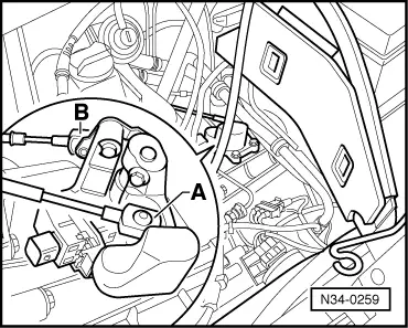
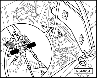
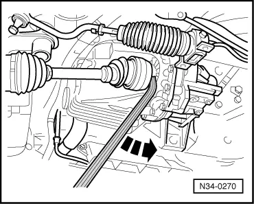
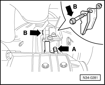
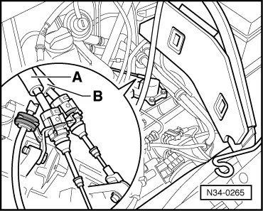
→ Installation position:

The gear selector cable -A- crosses over the gate selector cable -B-.

 
N34-0259
  • ‒ → Press gear selector cable -A- onto gear stick lever.
  • ‒ Press gate selector cable -B- onto gate selector lever.

  • ‒ Press pipe work into retainer on gearbox and insert into slave cylinder.
 
N30-0119
  • ‒ → Press in clip (arrow) for pipe work.
  • ‒ Install air cleaner.
  • ‒ Reconnect earth strap to battery.
  • ‒ Bleed clutch system.
  • ‒ Check gearbox oil .
  • ‒ Adjust gear change linkage .

Note:

Note radio coding for vehicles with coded radio.

 
N10-0039

Tightening torques

Gearbox to engine

80 Nm

Starter to gearbox and engine

45 Nm

Bolt and nuts -A- for steel pendulum support -1-

100 Nm

 
N34-0626

Nut -B- for aluminium pendulum support -1-

100 Nm

Shock absorber to coupling link

100 Nm

Wheel bearing housing to lower swivel joint

55 Nm

Drive shaft to wheel hub

150 Nm and turn 90°further

 
N34-0269

Wheel bolts to wheel hub

140 Nm

Track rod to steering arm

30 Nm and turn 90°further

Vehicles up to January 97

Centre bearing to bracket (arrows)

27 Nm

Vehicles from January 97

 
N34-0685

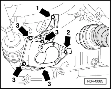
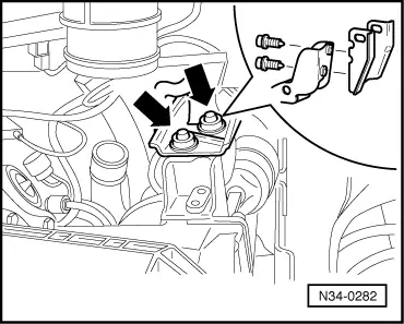
→ Support to engine/gearbox

Bolt -1-

45 Nm

Bolt -2-

20 Nm

Bolt -3-

45 Nm

  • ‒ First tighten bolts -arrows1 to 3- in ascending order hand tight, then tighten to tightening torque.

 
N34-0684

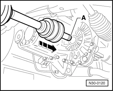
→ Axle shaft bearing to support

Bolts (arrows)

20 Nm

Continuation for all vehicles

Gearbox to body

 
N34-0281

Bolts -A-

20 Nm

Nut on bolt -B-

100 Nm

 
N34-0282

Bracket to gearbox console (arrow)

90 Nm

 
N34-0268

Engine mounting nuts (arrows)

50 Nm

Checking gearbox oil > < Adjusting gear selector mechanism