
Leon Mk1
| Layshaft: adjustment |
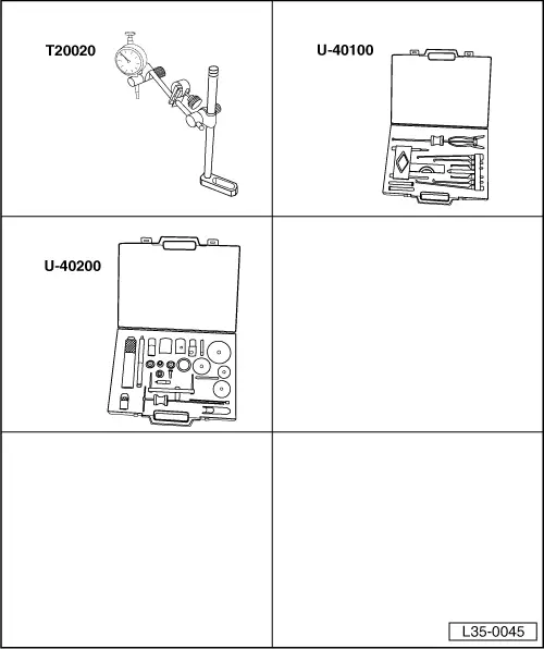
| Special tools and workshop equipment required |
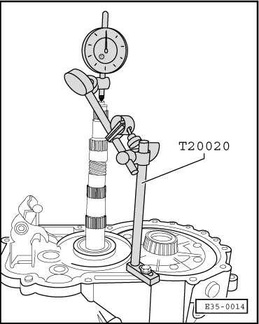
| t | Universal dial gauge bracket -T20020- |
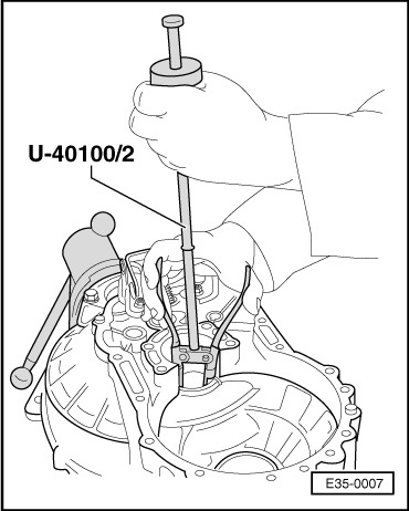
| t | Gearbox extractor set -U-40100- |
| t | Gearbox repair set -U-40200- |
|
|
|
 Note!
Note!
|
|
| Washer fitted | 0.65 mm |
| + Average value | 0.30 mm |
| + Pressure (const. value) | 0.20 mm |
| Shim thickness needed | 1.15 mm |
|
| Thickness (mm) | Spare no. |
| 0.65 0.70 0.75 0.80 0.85 0.90 0.95 1.00 1.05 1.10 1.15 1.20 1.25 1.30 1.35 1.40 | 020 311 391 P 020 311 391 Q 020 311 391 020 311 391 A 020 311 391 B 020 311 391 C 020 311 391 D 020 311 391 E 020 311 391 F 020 311 391 G 020 311 391 H 020 311 391 J 020 311 391 K 020 311 391 L 020 311 391 M 020 311 391 N |
|
|
|
|
|