seat Workshop Repair Guides

SEAT Workshop Service and Repair Manuals

Differential: Adjust > < Dismantling and assembling differential
Operation process
Operation process
   
Remove the outer ring of the tapered roller bearing from the clutch housing and gearbox casing
  Note
t  The procedure and tools needed to remove the secondary shaft rear bearings outer tracks, are identical in the gearbox casing and the clutch housing.
t  To remove the outer track of the clutch housing, first remove the socket for right hand flanged shaft → Fig..
  E39-10001
Install the outer ring of the tapered roller bearing to the clutch housing and gearbox casing
  Note
t  The procedure and tools needed to install the secondary shaft rear bearings outer tracks, are identical in the gearbox casing and the clutch housing.
t  No shim is installed on the clutch housing side.
  E39-0017
Removing the roller bearing
  Note
The procedure and tools needed to remove the secondary shaft rear bearings outer tracks, are identical in the gearbox casing and the clutch housing.
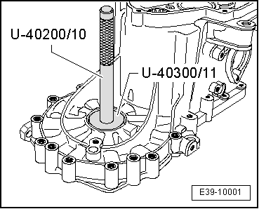
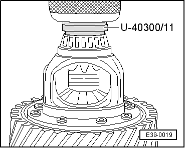
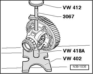
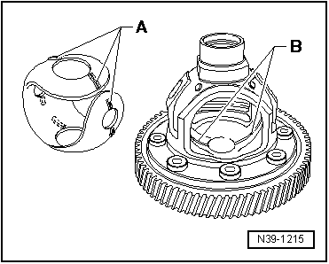
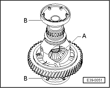
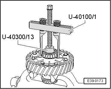
–  Locate adapter -U-40300/13- on differential.
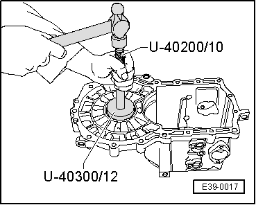
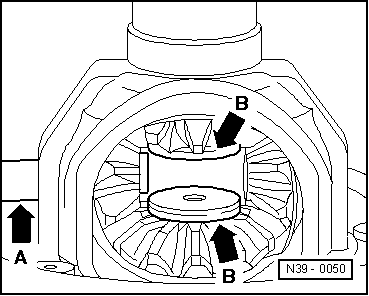
–  Place the bridge adaptor -U 40100/1- on adaptor -U-40300/13-, ensuring that the claws are inserted into the notches in the differential casing. Remove the bearing.
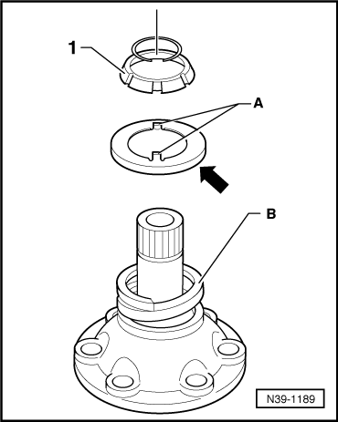
  Note
If the bearing cage breaks during the extraction then use the kit -T20022- to remove the inner ring of the bearing.
  E39-0173
Install the roller bearing
  Note
t  The procedure and tools needed to remove the roller bearings are identical for both sides of the differential box.
t  Before installing the bearing in the differential casing heat with electro-blower -SAT 1416- to 100 ºC. The temperature can be checked with digital thermometer -SAT 4013-.
–  Place adapter -U-40300/13- in a press.
–  Place differential assembly on the tool adapter -U-40300/13-.
–  Place adapter -U-40300/11- with side -B- facing the bearing, on the differential assembly.
  E39-0019
Spring pin identification
  V39-1635
Dim. „a“ mmIdentification
28.5 (short spring pin)
Removing and installing → Fig.
Circumferential groove -arrows-
36.0 (long spring pin),
Removing → Fig.,
Installing → Fig.
No circumferential groove

   
Allocation of differential cages
–  Check hole for spring pin in differential cage.
The hole in the differential cage was modified for the longer spring pin.
  N39-10272
BoreLength of spring pin (mm)
-A-28.5 (short spring pin)
-A- and -B-36.0 (long spring pin)

   
Spring pin with circumferential groove (short spring pin): Removing and installing
Removal:
–  Cover tapered roller bearing inner race and speedometer drive gear to avoid possible damage and ingress of metal particles.
–  Remove the tension sleeve using a chisel, apply pressure to the groove for this purpose.
Installation
–  Drive into differential cage to stop.
  V39-1649
Spring pin without annular groove (long spring pin): Removing differential pinion pin
The spring pin is sheared off when pressing out.
–  Drive remainder of spring pin out of differential cage.
  N39-1035
Installing spring pin without circumferential groove (long spring pin)
–  Align hole in differential pinion pin with hole in differential cage.
–  Drive in new spring pin with drift -1- until dimension -a- = 3.0 mm is attained.
l  The spring pin must not come in contact with gears with differential cage installed.
  N39-10050
In some gearboxes, the one-piece thrust washer has a shoulder -A- near the holes
In this case, the differential cage has a circumferential groove -B-.
–  Lubricate one piece thrust washer with gear oil and install.
–  Install one-piece thrust washer so that it engages in groove -B- in differential cage.
  N39-1215
Installing differential bevel gears
–  Coat the thrust washers with gearbox oil and fit in the differential casing.
–  Locate planet gears -A- and secure with articulation flanges -B-.
  E39-0051
–  Insert planet pinions offset 180° and pivot into position.
–  Press in differential pinion pin (-arrow A-) to first planet pinion.
–  Place threaded pieces -arrows B- in sun gears.
–  In this position, turn the satellites towards the inside of the differential box using the articulation flanges, until they coincide with the holes on the satellite shaft.
–  Fit the satellite shaft into its final position and install a new elastic pin to secure it.
  N39-0050
Installation position of thrust washer for tapered ring -1-
Collar -arrow- faces spring -B-.
Some gearbox versions have projections -A-.
The projections -A- face towards tapered ring -1-.
  N39-1189

Differential: Adjust > < Dismantling and assembling differential