
Leon Mk1
| Installation sequence - Cover for gearbox casing and 5th gear with the gearbox installed: Removing and installing |
| Consult the equivalence table for tools and equipment according to applicability among Seat / VW / Audi / Skoda → Chapter. |

| Special tools and workshop equipment required |
| t | Torque wrench kit -SAT 8010-, see equivalent → Anchor |
| t | Tray -T20173-, see equivalent → Anchor |
| t | Spanner -U 40090- |
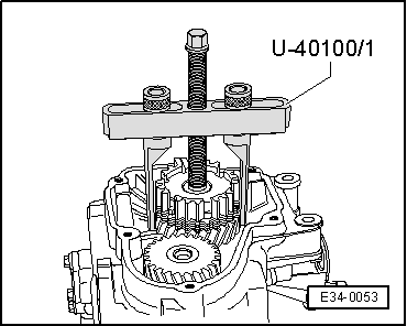
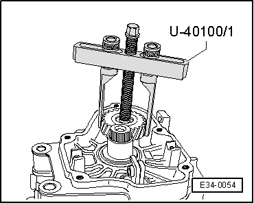
| t | Extractor kit -U 40100B-, see equivalent → Anchor |
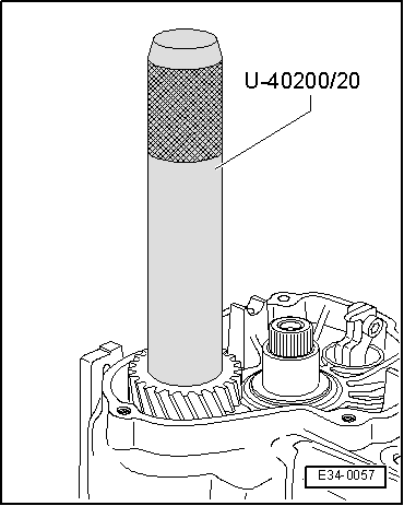
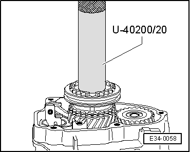
| t | Kit (case) -U 40200A-, see equivalent → Anchor |
| t | Hot air blower -SAT 1416-, see equivalent → Anchor |
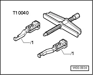
| t | Two arm puller -T10040- |
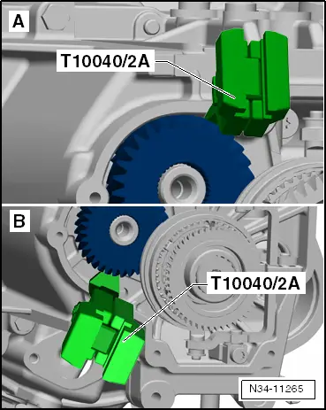
| t | With puller hooks -T10040/2A- |
|
|
 WARNING
|
|
|
|
 Caution
|
|
|
|
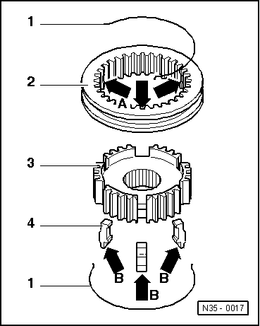
| Puller hooks -T10040/2A- cannot be inserted correctly. | |||||||
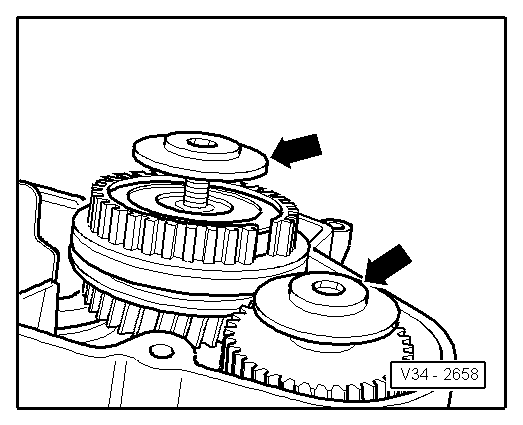
| -A- Puller hooks -T10040/2A- make contact too soon with:
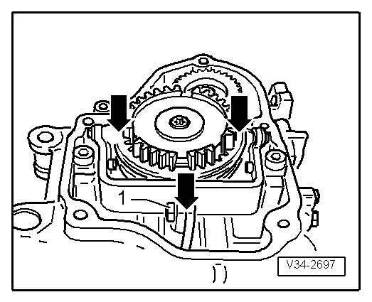
| Removing the „unit “: „synchro-hub for 5th gear“, „gear wheel for 5th gear“ and „gearbox housing“ → Chapter | ||||||
| -B- Puller hooks -T10040/2A- come into contact with ribs in gearbox housing below gear wheel. | |||||||
| Puller hooks -T10040/2A- cannot be inserted correctly. | |||
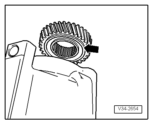
| 5th gear can be removed separately, ⇒ → Fig. |
 Note
Note
|
|
Note
|
|
|
|
|
|
|
|
|
|
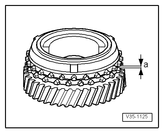
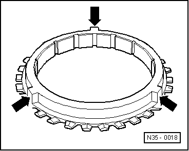
| Synchro-ring | Measurement „a“ on new synchroniser | Wear limit |
| 5. gear | 1,1 ... 1.7 mm | 0.5 mm |
|
Note
|
|
Note
|
|
|
|
|
|
|
|
Note
|
|
|
|
|
|
Note
|
|
|
|
|
|
|
|