
Leon Mk1
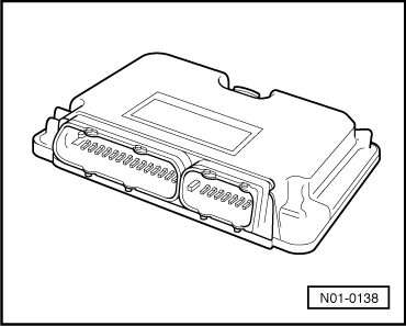
| Electrical/electronic components and their location |
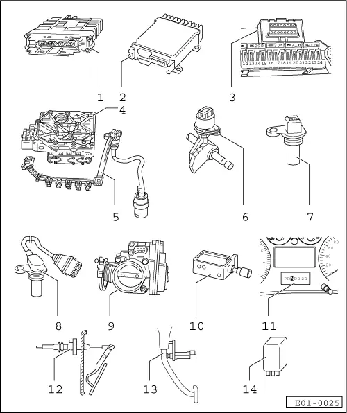
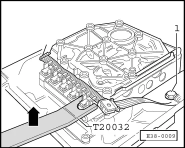
| 1 - | Automatic gearbox control unit -J217- |
| q | Location → Fig. |
| q | Separate → Fig. |
| q | Fit → Fig. |
| q | Checked by self-diagnosis → VAS 5051; Vehicle self-diagnosis |
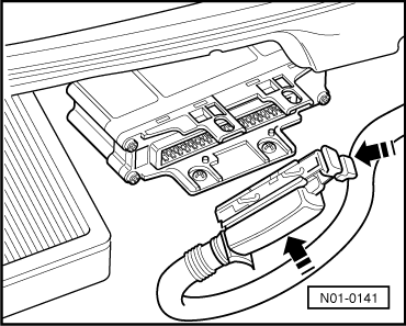
| 2 - | Engine control unit |
| q | Location → Fig. |
| q | Separate and fit → Rep. Gr.24 |
| q | If the control unit is replaced, the system has to be put in basic setting → VAS 5051; Vehicle self-diagnosis |
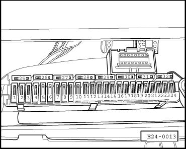
| 3 - | Connection for diagnosis |
| q | Location → Fig. |
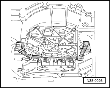
| 4 - | Slide box |
| q | Location → Fig. |
| q | The solenoid valves -N88-, -N89-, -N90-, -N91-, -N92-, -N93- and -N94- are fitted to the slide box |
| q | The valves are checked by self-diagnosis → VAS 5051; Vehicle self-diagnosis |
| 5 - | Conducting plate with incorporated gearbox oil temperature sender -G93- |
| q | Location → Fig. |
| q | Separating and fitting → Fig. |
| q | The oil temperature sender -G93- is checked by self-diagnosis → VAS 5051; Vehicle self-diagnosis |
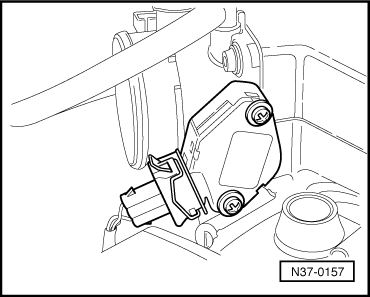
| 6 - | Multi-function switch -F125- |
| q | Location → Fig. |
| q | Separate and fit → Fig. |
| q | The multi-function switch -F125- is checked by self-diagnosis → VAS 5051; Vehicle self-diagnosis |
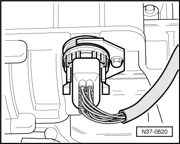
| 7 - | Gearbox rev. speed sender -G38- |
| q | Location → Fig. |
| q | Separate and fit → Fig. |
| q | The sender -G38- is checked by self-diagnosis → VAS 5051; Vehicle self-diagnosis |
| 8 - | Road speed sender -G68- |
| q | Location → Fig. |
| q | Separate and fit → Fig. |
| q | The sender -G68- is checked by self-diagnosis → VAS 5051; Vehicle self-diagnosis |
| 9 - | Throttle valve potentiometer -G69- |
| q | The throttle valve potentiometer signal is checked by self-diagnosis |
| q | Location and additional information on the potentiometer and its removal and fitting → Fig. |
| q | The throttle valve potentiometer -G69- is checked by self-diagnosis → VAS 5051; Vehicle self-diagnosis |
| 10 - | Electromagnet for gear lever locking -N110- |
| q | Location → Fig. |
| q | Separate and fit → Chapter |
| q | The electromagnet for gear lever locking -N110- is checked by self-diagnosis → VAS 5051; Vehicle self-diagnosis |
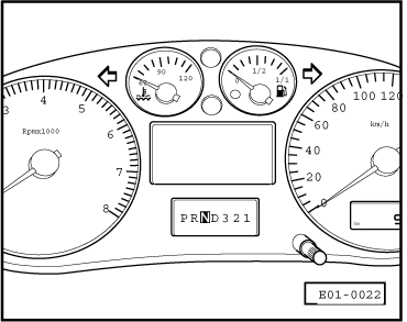
| 11 - | Gear lever range display -Y5- |
| q | Location → Fig. |
| 12 - | Kick-down switch -F8- |
| q | Location and additional information on the kick-down switch and its separation and fitting → Fig. |
| q | The multi-function switch -F8- is checked by self-diagnosis → VAS 5051; Vehicle self-diagnosis |
| 13 - | Brake light switch |
| q | Location → Fig. |
| q | Separate and fit → Fig. |
| q | The electromagnet for gear lever locking -N110- is checked by self-diagnosis → VAS 5051; Vehicle self-diagnosis |
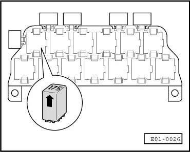
| 14 - | Relay for starter blocking and reversal light -J226- |
| q | Location → Fig. |
|
|
|
|
|
|
|
|
|
|
|
|
|
|
|
|
|
|
|
|
|
|
|
|
|
|
|
|
|
|
|
|
|
|