seat Workshop Repair Guides

SEAT Workshop Service and Repair Manuals

Measured value blocks > < Final control diagnosis
Final control diagnosis: carrying out
   
Final control diagnosis: carrying out
The final control diagnosis activates the following components in the stated sequence:
l  Throttle valve positioner -V60-
l  Solenoid valve 1 for activated charcoal filter -N80-
l  Engine speed signal
l  Fuel pump relay -J17-
l  Engine/air conditioning compressor electrical connection (not relevant)
Special tools and workshop equipment required
t  Hand multimeter -V.A.G 1526 A- or multimeter -V.A.G 1715-
t  Diode test lamp -V.A.G 1527 B-
t  Fault reader -V.A.G 1551- or vehicle system tester -V.A.G 1552- with cable -V.A.G 1551/3B-
t  Auxiliary measuring set -V.A.G 1594 C-
t  Test box -V.A.G 1598/18-
t  Current flow diagram

Checking conditions
   
l  The fuses 15, 18, and 21, OK.
  Note!
If it is necessary to repeat the final control diagnosis, without first running the engine briefly, switch the ignition off for approx. 20 seconds.
Work sequence
–  Connect fault reader -V.A.G 1551- (-V.A.G 1552-) and select engine electronics control unit with the “Address code” 01. The ignition must be switched on. (Fault reader: Connecting and selecting the engine electronics control unit → Chapter.)
  E01-0119
Indicated on the display:
–  Operate the fault reader taking into account the information on the display:
–  Press keys 0 and 3 for the function “Final control diagnosis”.
 
Rapid data transfer                 HELP
Select function XX                      
Indicated on the display:
–  Confirm entry with the Q key.
 
Rapid data transfer                    Q
03-Final control diagnosis              
Indicated on the display:
   The throttle valve positioner must open and close the throttle valve until switching to the next final control by pressing the key.
If the throttle valve positioner does not move:
–  Check the throttle valve positioner → Chapter, Throttle valve control unit: checking
Activating activated charcoal filter solenoid valve 1 -N80-:
–  Press the key.
 
Final control diagnosis               ->
Throttle valve positioner V60           
Indicated on the display:
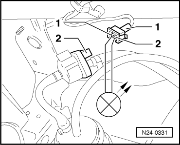
   The activated charcoal filter solenoid valve 1, located in the right wheel housing, must be activated intermittently until the final control diagnosis is ended by pressing the key.
–  Pull the hose off activated charcoal filter at the solenoid valve.
–  Connect an auxiliary hose to the vacant valve connection.
–  Blow into auxiliary hose during final control diagnosis (in direction of throttle valve control unit). Valve must open and close
If the solenoid valve does not click:
–  Continue check → 
Displaying engine speed signal:
  Note!
This test is only possible on vehicles with rev counter. On vehicles without rev. counter, switch to the next final control by pressing the key when the following message is displayed.
–  Press the key.
 
Final control diagnosis               ->
Activat. charc. filter solen. valve  N80
Indicated on the display:
   Rev. counter should show approx. 3,000 rpm, until next final control element is activated by pressing the key.
If no display appears:
–  Perform idling speed check. → Current flow diagrams, Electrical fault finding and Fitting locations
Activating fuel pump relay -J17-:
–  Press the key.
 
Final control diagnosis               ->
Engine speed signal                     
Indicated on the display:
   The fuel pump relay (on the relay plate with fuseholder, relay position 12) must click until the next final control is activated by pressing the key.
  Note!
During the activation of the fuel pump relay, the fuel pump must be audible at intervals.
If the relay does not click:
–  Check fuel pump relay. → Current flow diagrams, Electrical fault finding and Fitting locations
–  Press the key.
Check electrical connection with air conditioning:
  Note!
The test step is only for vehicles with air conditioner. On vehicles without air conditioner, end final control diagnosis by pressing key when the following message appears.
 
Final control diagnosis               ->
Fuel pump relay J17                     
Indicated on the display:
   The air conditioner compressor magnetic coupling must click, until entering final control diagnosis by pressing key.
If the magnetic coupling does not click:
–  Check air conditioning: → Heating, air conditioning; Rep. Gr.87
–  Press the key.
 
Final control diagnosis               ->
Engine/Air cond. compr., electr. connec.
Indicated on the display:
–  Press keys 0 and 6 for the “End output” function and confirm input with the Q key.
–  Switch ignition off.
  Note!
Once the final control diagnosis is completed, switch off ignition. If ignition is not disconnected before switching on the engine again, the engine will not start because neither the injectors nor the ignition transformer will be activated.
Continuation of check when the activated charcoal filter solenoid 1 does not click:
 
Rapid data transfer                 HELP
Select function XX                      
–  Pull connector -1- off solenoid valve -2- and connect diode test lamp -V.A.G 1527 B- with aux. cables from -V.A.G 1594 C- to disconnected connector.
   The LED must flash (bright/dark).
LED flashes:
–  Proceed with final control diagnosis until completed.
–  Switch ignition off.
–  Renew solenoid valve -2-: → Rep. Gr.20.
LED does not flash:
–  Proceed with final control diagnosis until completed.
–  Switch ignition off.
  N24-0331
–  Connect test box -V.A.G 1598/18- to control unit wiring harness.
–  Check wiring between test box socket 3 + double connector contact 1 for open circuit using the current flow diagram.
   Wire resistance: 1,5 Ω max.
–  Also check the wire for short circuits to battery positive and earth.
   Specification: ∞ Ω
–  Check wire between 2-pin connector, contact 2 and the relay plate for open circuit using the current flow diagram.
   Wire resistance: 1,5 Ω max.
If no wiring fault is detected:
–  Renew engine control unit 1AV -J382- → Chapter
  N24-0334

Measured value blocks > < Final control diagnosis