
Leon Mk1
| Valve control: repairing |
 Note!
Note!| t | The cylinderheads with cracks between the valve seats can still be used without decrease in their useful life, so long as the cracks are no wider than 0.5 mm max. |
| t | Before installation work, oil the support and slide surfaces. |
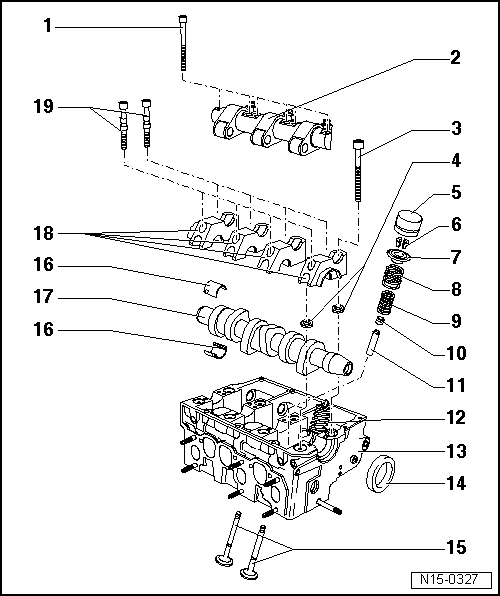
| 1 - | 20 Nm + 1/4 turn (90°) |
| q | Replace |
| q | Follow the installation order when loosening and tightening → Fig., Camshaft: removing and installing |
| 2 - | Rocker shaft |
| 3 - | Cylinderhead bolt |
| q | Replace |
| q | Follow the installation order when loosening and tightening → Anchor, Cylinderhead: removing and installing |
| q | Before installation, fit the washers → Item in the cylinderhead |
| 4 - | Washer |
| q | For the cylinderhead bolts |
| 5 - | Hydraulic plunger |
| q | Before removing, remove the half-bearings of the camshaft |
| q | Do not swap them |
| q | With hydraulic compensation of valve play |
| q | Place with the slide surface down |
| q | Before installation test the axial play of the camshaft → Fig. |
| q | Lubricate the slide surface |
| 6 - | Half-cones |
| 7 - | Valve spring plate |
| 8 - | Valve spring, exterior |
| q | Remove and install: Cylinderhead: removed: with -T20034/1- installed: → Item, replace the valve stem seals |
| 9 - | Valve spring, interior |
| q | Remove and install: Cylinderhead: removed: with -T20034/1- installed: → Item, replace the valve stem seals |
| 10 - | Valve stem seal |
| q | Replace → Item |
| 11 - | Valve guide |
| q | Test → Item |
| q | Replace → Item |
| q | Repair guides, with collar |
| 12 - | Pump injector |
| q | Remove and install → Chapter |
| 13 - | Cylinderhead |
| q | Bear in mind the note → Anchor |
| q | Re-cut the valve seats → Chapter |
| 14 - | Seal |
| q | Do not apply more oil or grease to the seal lip |
| q | Before installation, clean excess oil from the camshaft journal with a clean cloth |
| q | For installation, cover the slot in the camshaft cone (e.g. with tape) |
| q | Remove and install → Chapter |
| 15 - | Valves |
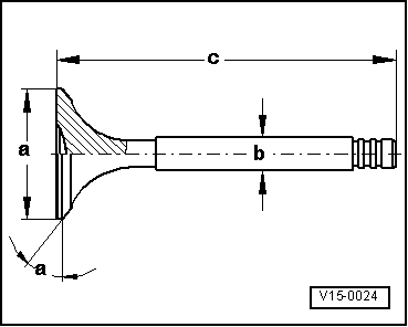
| q | Valve dimensions → Fig. |
| 16 - | Half-bearings |
| q | Do not swap the used half-bearings (mark them) |
| q | Check that the cylinderhead and the fixing flanges fit well in the caps |
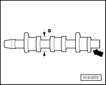
| 17 - | Camshaft |
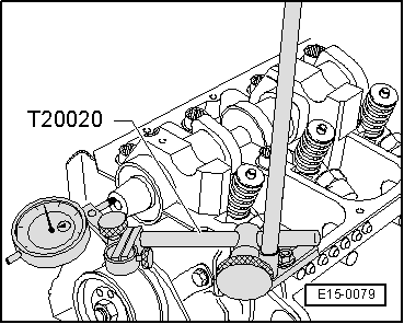
| q | Test the axial play → Fig. |
| q | Remove and install → Fig. |
| q | Test the radial play with Plastigage Wear limit: 0.11 mm |
| q | Eccentricity: max. 0.01 mm |
| q | Identification and distribution timing → Fig. |
| 18 - | Cap |
| q | Installation order → Fig., Camshaft: removing and installing |
| q | Cap 4 is marked as cap 5 |
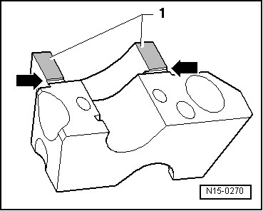
| q | For installation, seal the contact surfaces of caps 1 and 4 with -AMV 17400401- → Fig. |
| 19 - | 20 Nm + 1/4 turn (90°) |
| q | Replace |
Note!
|
|
Note!
|
|
| Dimension | Intake valve | Exhaust valve | |
| Ø a | mm | 35.95 | 31.45 |
| Ø b | mm | 6.980 | 6.956 |
| c | mm | 89.95 | 89.95 |
| α | ∠° | 45 | 45 |
|
|
| Cylinder 3 -arrow- | 045 C | ||
|
| Intake opens after TDC | 15.8° | ||
| Intake closes after BDC | 25.3° | ||
| Exhaust opens before BDC | 28.2° | ||
| Exhaust closes before TDC | 18.7° | ||