seat Workshop Repair Guides

SEAT Workshop Service and Repair Manuals

Engine: Removing and installing > < Engine data
Engine: dismounting
Engine: dismounting
  Note
t  To carry out this work it will be necessary to disconnect battery earth strap. Check whether a coded radio is fitted. Where necessary, check the anti-theft coding first.
t  The engine is removed from underneath together with the gearbox.
t  All the cable fixings that are opened or cut during removal of the cylinder head must be fitted in the same position when reinstalling the engine.
t  Collect drained coolant in a clean container for re-use or disposal.
t  Some components can not be removed, or only with a great deal of difficulty, while the engine is mounted. Therefore the fault memory should be consulted → Chapter, to detect all the faulty components while the engine has been removed, and to replace them before the engine is reassembled.
  WARNING
When doing any repair work, especially in the engine compartment, pay attention to the following due to the cramped conditions:
Route all the various lines (e.g. for fuel, hydraulics, active carbon filter system, coolant, refrigerant, brake fluid and vacuum pipes and hoses) and electrical wiring so that the original positions are restored.
Ensure that there is sufficient clearance to all moving or hot components.
   
Operation process
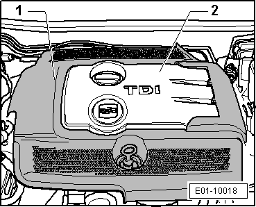
–  Detach the outer -1- and inner -2- engine covers, by pulling them evenly upwards.
  WARNING
Observe safety precautions when disconnecting the battery → Electrical system; Rep. gr.27.
–  With ignition switched off, disconnect earth connection from battery.
–  Remove battery and battery bracket → Electric system; Rep. gr.27
–  Remove air filter → Chapter.
  WARNING
Hot vapour/hot coolant may escape when opening expansion tank. Cover cap with cloth and open carefully.
–  Open cap on coolant expansion tank.
–  Remove front right-hand wheel.
  E01-10018
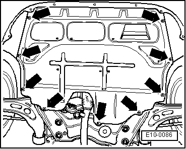
–  Release the fasteners -arrows- to remove the central soundproofing panel.
  E10-0086
–  Unscrew the bolts -arrows- and remove the heat protecting plate.
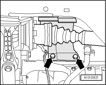
–  Unbolt the articulated shaft on the right and left sides from the gearbox and tie up → Running gear, shafts, steering; Rep. gr.40.
  A10-0921
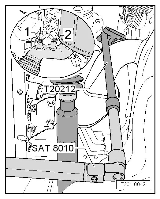
–  Unbolt the pressure pipe -2- using the articulated wrench E/C 17 -T20212-.
–  Unbolt the temperature sender after the particulate filter -G527--1- using the articulated wrench E/C 17 -T20212-.
–  Drain coolant → Chapter.
  WARNING
The fuel and the fuel lines may become excessively hot (burn risk).
The fuel supply system is also under pressure. Before opening the system, place a cloth over the junction and depressurise the system by gently loosening.
For all assembly work carried out on the fuel supply system, protective glasses and gloves must be worn!
  E26-10042
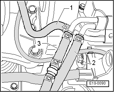
–  Separate the fuel feed and return lines -2- and -3- .
–  Separate the coolant lines -1- .
  E10-0090
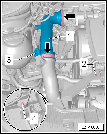
–  Separate the clamps -arrows- and remove the supercharger hose -1-.
–  Disconnect connection -3- from the intake manifold air pressure sender -G71-.
  E21-10036
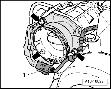
–  Detach electrical connector -1- of the engine intake manifold flap -V157-.
–  Unscrew the bolts -arrows- and remove the intake manifold flap motor -V157-.
  Note
For improved understanding, it is shown from the rear in the illustration with engine removed.
  A10-10029
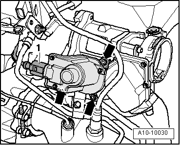
–  Disconnect the electrical connector -1- on the exhaust gas recirculation valve -N18- with the potentiometer for regulating exhaust gases -G212-.
–  Remove the electrical harness from the brackets and move to one side.
–  Remove bolts -arrows-.
–  Remove the exhaust gas recirculation valve -N18- with the potentiometer for exhaust gas recirculation -G212- from the intake manifold.
  A10-10030
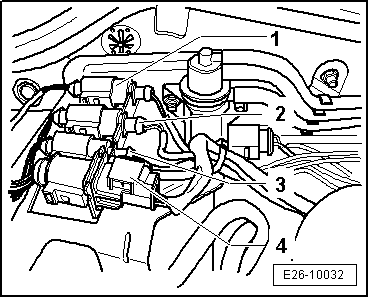
–  Disconnect the connectors -1-, -2-, -3- and -4- and remove them from their housings.
  E26-10032
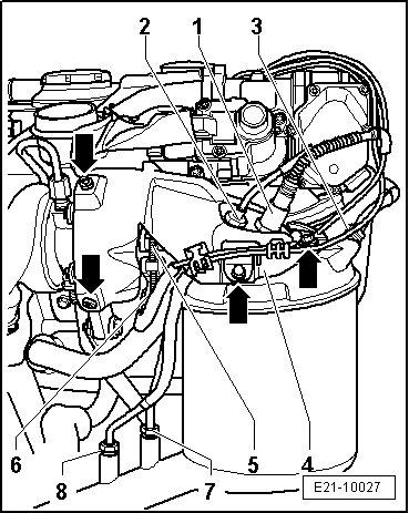
–  Undo the pressure pipe -3- of the particulate filter using the socket wrench E/C 17 -T20211-.
–  Undo the lambda probe -G39--1- using the socket wrench E/C 22 -T20202A- and the "ratchet 1/2" x 9-12" -VAG 1331/1-.
–  Unscrew the bolts -arrows- and free heatproof plate of the particulate filter -4- without removing it.
  E21-10027
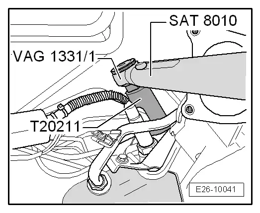
–  Undo the exhaust gas temperature sender 2, bench 1 -G448--2- using the socket wrench E/C 17 -T20211- and the "ratchet 1/2" x 9-12" -VAG 1331/1-.
  E26-10041
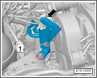
–  Disconnect the electrical connector -arrow- for temperature sender 1 of the exhaust gases -G450-.
–  Undo the nuts -1- and remove the exhaust gas pressure sensor 1 -G450- together with the pressure pipes.
  E10-10057
–  Unscrew the bolts -2- and -4- to free the bottom of the super charger rigid hose.
  E21-10036
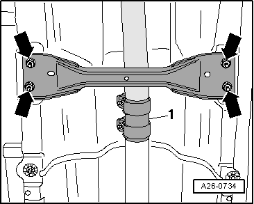
–  Unscrew the nuts on the double clamp -1-. In that case it is not necessary to unscrew nuts -arrows-.
  Note
The flexible pipe connection (de-coupling element) in the front exhaust pipe must not be bent more than 10° - otherwise it can be damaged.
  A26-0734
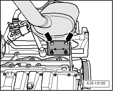
–  Remove the support bolts of the particle filter and the engine block, and remove the support.
–  Remove the front exhaust section from the tunnel bridge → Item.
  Note
t  The mounting on the front section of the exhaust pipe with particle filter should not be bent by more than 10° otherwise there is a risk of damage.
t  Pay attention to the electrical connections and routing the cables without damaging.
–  Remove the front part of the exhaust pipe with the particulate filter and place it on the power steering.
–  Remove coolant hoses from radiator.
–  Separate the coolant tubes going to the heat exchanger.
–  Separate the refrigerant tube from the coolant expansion tank.
  A26-10190
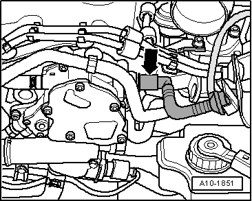
–  Extract the vacuum hose to the brake servo from the tandem pump -arrow-.
–  Release all low pressure hoses.
  A10-1851
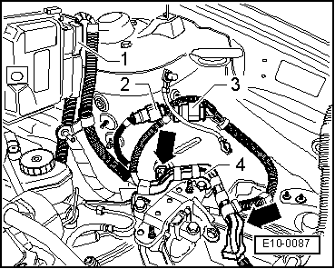
–  Remove the connector -1- of the engine control unit and connectors -2- and -3-, unfasten -arrows- the cable mounting -4- (depending on vehicle equipment).
–  Unscrew the earth connection on the front left strut.
  E10-0087
–  Unplug connector -2-.
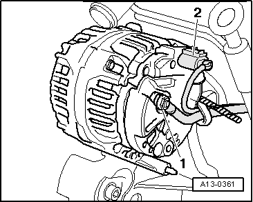
–  Unscrew the electrical cable nut -1- and the cable bracket.
  A13-0361
–  Unscrew earth connection -1-.
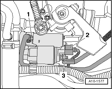
–  Detach wires -2- and -3- from starter motor.
  A10-1577
–  Separate the connector -3- and remove it from the bracket -1-.
–  Remove the electric reverse gear switch from the gearbox.
–  Unplug the coolant fan thermal switch -F18- connector and the radiator fan connector.
–  Move all electric cables to one side.
–  Remove the gear control cables from the gearbox → Rep. gr.34
–  Remove the clutch master cylinder without opening the hydraulic circuit, and leave to one side (the clutch pedal should not be pressed) → Rep. gr.30
  Note
Do not press the clutch pedal
–  Remove front bumper covering → Bodywork, exterior installation work; Rep. gr.63.
–  Bring lock plate carrier into service position: → Bodywork, exterior fitting work; Rep. gr.50.
Vehicles with air conditioner
  Caution
The air conditioning refrigerant circuit must not be opened.
To avoid damage to the condenser and refrigerant pipes/sleeves, take care not to bend, twist or stretch the pipes/sleeves excessively.
  Note
For removal and installation of the engine there is no need to open the refrigerant circuit.
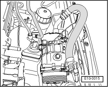
–  Remove the clip/s from the refrigerant hose/s.
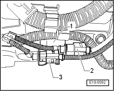
  E10-0092
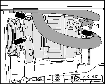
–  Disconnect electrical connection -1- for magnetic coupling on air conditioner compressor.
–  Remove compressor bolts -arrows-.
  A10-1637
–  Leave the air conditioning compressor with refrigerant hoses still connected suspended above, secure it to the lock carrier plate; take special care not to damage the system.
  E10-0015
All other vehicles continued
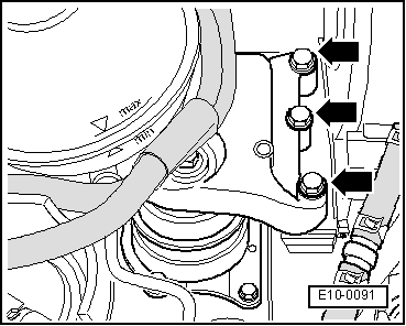
–  Loosen the bolts -arrows- fastening the mountings to the engine by a couple of turns.
  E10-0091
–  Loosen the bolts -arrows- fastening the mountings to the gearbox by a couple of turns.
–  Remove the connection tube between the intercooler and the exhaust gas turbocharger → Item .
  WARNING
Cover the intercooler opening, for example, using a clean cloth made of spongy material so that coolant does not enter.
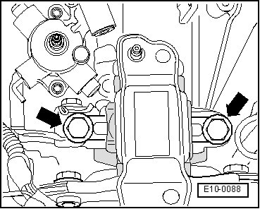
  E10-0088
–  Unscrew bolts -arrows- and remove pendulum arm support.
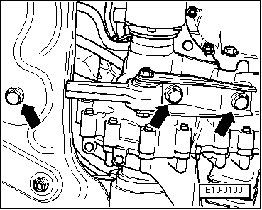
  E10-0100
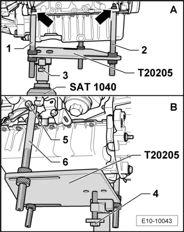
–  Bring the securing tool -T20205- with the hydraulic jack -SAT 1040- and turn the bolt -4- until it is parallel with the engine block.
–  From the rear of the engine -A-, first insert the fixed column -1-, then adjust the mobile column -2- as necessary and then screw on the nuts -arrows-.
–  From the front of the engine -B-, position the mobile column -6- and adjust the bolt -5-.
–  Adjust the bolt -3- to immobilise the securing tool -T20205-.
  Note
To unscrew the bolts for gearbox mounting use the step ladder.
  E10-10043
–  Remove bolts -arrows- fastening mountings to engine.
  E10-0091
–  Remove bolts -arrows- fastening mountings to gearbox.
  Note
t  Ensure that all hose attachments and tubes between the engine, gearbox and the body have been loosened.
t  To avoid damage, guide the engine/gearbox mounting carefully when lowering.
–  Carefully lower the engine and gearbox.
–  Pull engine/gearbox assembly as far as possible forwards and lower it slowly downwards.
  E10-0088

Engine: Removing and installing > < Engine data