
Leon Mk1
| Parts of cooling system, engine side |
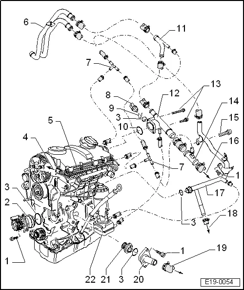
| 1 - | 15 Nm |
| 2 - | Coolant pump |
| q | Check for ease of movement |
| q | Note fitting position: |
| q | Removing and installing → Chapter |
| 3 - | O ring |
| q | Renew |
| 4 - | Towards the upper part of the expansion tank |
| q | Coolant hose schematic diagram → Chapter. |
| 5 - | Upper metal tube for coolant |
| q | screwed onto the cylinder head cover |
| q | Coolant hose schematic diagram → Chapter. |
| 6 - | Joint mouth |
| q | For the heat exchanger |
| 7 - | Distribution element |
| 8 - | Coolant temperature sender -G62- |
| q | With coolant temperature gauge sender -G2- |
| 9 - | Retaining clip |
| q | Ensure correct seating |
| 10 - | O ring |
| q | Renew |
| 11 - | Distribution element |
| 12 - | Joint mouth |
| 13 - | 10 Nm |
| 14 - | Distribution element |
| 15 - | 40 Nm |
| 16 - | To radiator by the upper part |
| q | Coolant hose schematic diagram → Chapter. |
| 17 - | Metal pipe for Coolant |
| q | Coolant hose schematic diagram → Chapter. |
| 18 - | Towards the lower part of the expansion tank |
| q | Coolant hose schematic diagram → Chapter. |
| 19 - | To radiator, down |
| q | Coolant hose schematic diagram → Chapter. |
| 20 - | Joint mouth |
| q | For thermostat. |
| 21 - | Coolant thermostat: |
| q | Removing and installing → Chapter |
| q | Note installation position → Chapter |
| q | Check: heat the thermostat in water |
| q | Starts opening at approx. 85 ℃ |
| q | Ends at approx. 105 °C. |
| q | Opening lift at least 7 mm. |
| 22 - | Oil cooler |
| q | Removing and installing → Item |