seat Workshop Repair Guides

SEAT Workshop Service and Repair Manuals

Fuel supply, gas operation > < Cooling system: checking for leaks
Draining and filling cooling system
t  Empty → Anchor
t  Filling → Anchor
Consult the equivalence table for tools and equipment according to applicability among Seat / VW / Audi / Skoda → Chapter.
   
Special tools and workshop equipment required
t  Measuring tool -T10007-, see equivalent → Anchor
t  Collecting tray -T20173-, see equivalent → Anchor
t  Base -T20174-, see equivalent → Anchor
t  Adapter -VAG 1274/8-, see equivalent → Anchor
t  Coolant charger -VAS 6096-, see equivalent → Anchor

Draining
  WARNING
Hot steam/hot coolant can escape - risk of scalding.
The cooling system is under pressure when the engine is hot.
Steam may be released when opening the expansion tank. Cover the cap with a cloth and open carefully.
  Note
Collect drained coolant in a clean container for re-use or disposal.
–  Open cap on coolant expansion tank.
   
–  Release the fasteners -arrows- to remove the central soundproofing panel.
–  Place the drip tray -T20173- under the engine.
  E10-0086
–  Remove the connecting hose »hot side«. For this purpose loosen hose clamp -Arrows-.
  Note
Block the intercooler with a clean cloth to prevent coolant from entering.
  N21-10326
–  Drain the coolant by loosening the spring flange on the lower sleeve of the radiator.
  N19-10340
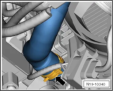
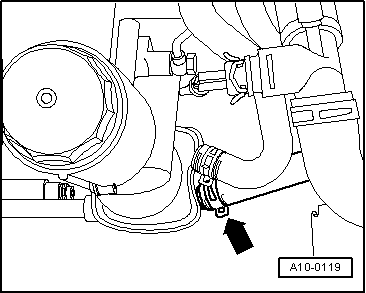
–  To drain coolant from engine also remove coolant hose from oil cooler -arrow-.
  Note
Please observe requirements for disposal.
Top up
  Note
t  
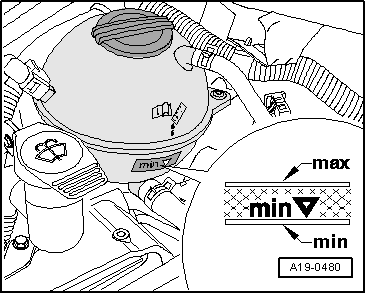
The cooling system is filled all year round with a mixture of water and coolant additive (combined anti-freeze and corrosion protection agent).
t  Only use coolant additive Plus -G 012 A8F A1- (»abbreviated: G12+«), „according to TL VW 774 F“. Other coolant additives could seriously impair in particular the anti-corrosion properties. The resulting damage could lead to loss of coolant and consequently to serious engine damage.
t  Coolant additive »G12+« can be mixed up with additives »G11« and »G12«.
t  »G12+« and coolant additives marked „Conforming with specification TL VW 774 F“ prevent frost and corrosion damage and stop scale from forming. Such additives also raise the boiling point of the coolant. For these reasons the cooling system must be filled all year round with the correct antifreeze and anticorrosion additive.
t  Thanks to this rise in the boiling point, the coolant guarantees good running, even when the engine undergoes heavy strain, especially in countries with tropical climates.
t  Frost protection is required down to about -25 ℃ (in countries with arctic climate: down to about -35 ℃).
t  The concentration of the coolant must not be reduced by adding water in summer or in countries with hot climates. The amount of anti-freeze in the coolant must be at least 40 %.
t  If for climatic reasons a greater frost protection is required, the amount of »G12+« can be increased, but only up to 60 % (frost protection to about -40 °C), as otherwise frost protection is reduced again and cooling effectiveness is also reduced.
t  To mix up the coolant use clean drinking-water only.
t  If radiator, heat exchanger, cylinder head, cylinder head gasket or cylinder block is replaced, do not reuse old coolant.
t  Contaminated or dirty coolant must not be used again.
t  
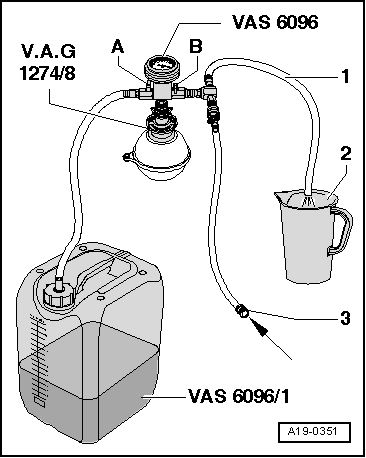
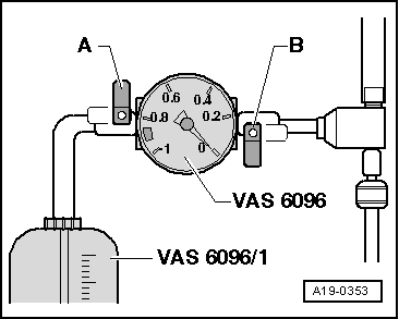
Use the refractometer -T10007- to check frost protection of coolant additive »G12+« in the cooling system.
Recommended mixture ratios:
  A10-0119
Anti-freeze protection untilAntifreeze ratio.G 12 → RemarkQuantity of water → Remark
-25 ℃
-35 ℃
40 %
50 %
3.2 l
 4.0 l
4.8 l
 4.0 l

1)  Coolant quantity may vary depending on the vehicle equipment
–  Tighten the spring flange on the lower sleeve arrow of the radiator.
   
–  Connect the cooling liquid hoses to the oil cooler -arrow-.
  A10-0119
–  Fill coolant reservoir -VAS 6096/1- with at least 8 l premixed coolant of the right mixture ratio:
l  »G12+« (60 %) and water (40 %), for a protection to -25 ℃
l  »G12+« (50 %) and water (50 %), for a protection to -35 ℃
l  »G12+« (60 %) and water (40 %), for a protection to -40 ℃
–  Screw on adaptor -VAG 1274/8- to the coolant expansion tank.
–  Fit the coolant charger -VAS 6096- onto the adaptor -VAG 1274/8-.
–  Run vent hose -1- into a small container -2-. When flashing off a small quantity of coolant is carried away, which is to be collected.
–  Connect both valves -A- and -B- (lever arm transverse to direction of flow).
–  Connect hose -3- to compressed air.
l  Pressure: 6…10 bar
  A19-0351
–  Open valve -B- (lever arm pointing in direction of flow).
The suction jet pump creates a vacuum in the cooling system.
l  The display instrument needle must move to the green area.
–  Also briefly open valve -A- (turn lever in direction of flow) so that the coolant charger -VAS 6096- hose can fill with coolant.
–  Close valve -A- again.
–  Leave valve -B- open for another 2 minutes.
l  The suction jet pump creates further vacuum in the cooling system.
l  The pointer of the indicator must remain in the green zone.
–  Close valve -B-.
l  The display instrument needle must remain in the green area so that the vacuum in the cooling system is sufficient to continue with the refilling.
If the needle does not reach the green zone, repeat the process.
If the vacuum drops the cooling system is leaking.
–  Pull out pressure hose.
–  Open valve -A-.
The vacuum in the cooling system causes the coolant to be drawn out of the cooling system charge unit -VAS 6096/1-; the cooling system is then filled.
  A19-0353
–  Check the coolant level and top up coolant as far as the MAX mark.
–  Start engine and run at approx. 1500rpm for max. 2 minutes and at the same time fill with coolant up to overflow hole on expansion tank.
–  Screw on cap on coolant expansion tank.
–  Run engine until radiator fan cuts-in.
  WARNING
Hot vapour/hot coolant may escape when opening expansion tank. Cover cap with cloth and open carefully.
–  Check coolant level and top-up if necessary.
l  When the engine is at normal working temperature, the coolant should be at the max. mark and, when the engine is cool, between the min and max marks.
–  Switch off the engine.
  A19-0480

Fuel supply, gas operation > < Cooling system: checking for leaks