seat Workshop Repair Guides

SEAT Workshop Service and Repair Manuals

Engine control unit > < O-rings for the injection pump: removing and fitting
Injector pump: removing and fitting
t  Removing → Anchor
t  Installing → Anchor
Consult the equivalence table for tools and equipment according to applicability among Seat / VW / Audi / Skoda → Chapter.
   
Special tools and workshop equipment required
t  1/2" xzn wrench spanner kit -SAT 1006/2-, see equivalent → Anchor
t  Torque wrench kit -SAT 8010-, see equivalent → Anchor
t  Extractor -T10055A-, see equivalent → Anchor
t  Socket -T20020-, see equivalent → Anchor
t  Measuring tool -T20110B-, see equivalent → Anchor

Removing
–  Remove cylinder head cover → Chapter.
  Note
   
To increase the time between services, the injector pump adjustment bolts -1- and the spherical head pin -2- have been modified. In the older engines, the modified versions may be mixed with the older versions.
–  Rotate the crankshaft until the pair of cams for the injector pump that are to be removed point upwards in a uniform manner.
  N23-0430
–  Loosen the counter nuts for the adjustment bolts -1- and unscrew the adjustment bolts to the point that the rocker rests on the pressure spring for the injection pump unit.
–  Using the respective ball head tool from the 1/2" xzn socket wrench kit -SAT 1006/2-, remove the bolts -2- for the rocker arm, from the outside to the inside and remove the rocker arm shaft.
–  Using the respective ball head tool from the 1/2" xzn socket wrench kit -SAT 1006/2-, unscrew the bolt -3- which secures the mounting bracket and remove the latter case.
  N23-0343
–  Lever connector off injector-pump unit with a screwdriver -arrow- . In order to avoid twisting, press lightly with a finger on the opposite side of the connector.
  A23-0134
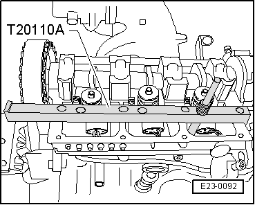
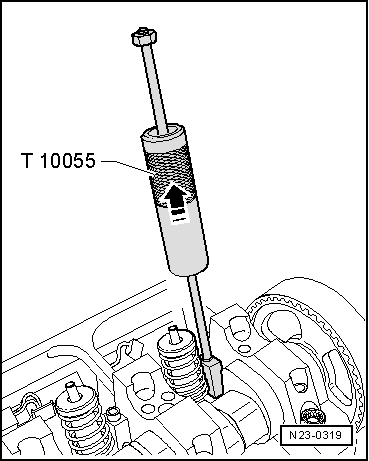
–  Fit the extractor -T10055A- into the slot on the side of the injector pump instead of the attachment block.
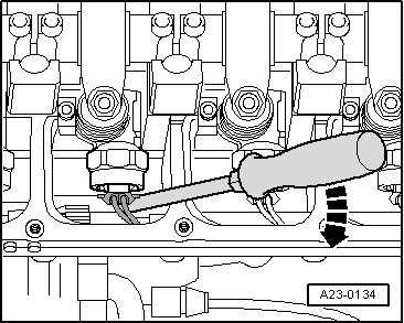
–  Carefully pull injector-pump assembly out of cylinder head seat with gentle taps
Installing
  Note
t  New injection pumps are supplied with O-rings and the thermal protection joint.
t  If a new injector pump unit is being fitted, the corresponding adjustment bolt on the rocker must also be replaced.
t  When a used injection pump is refitted, the O-rings and the thermal protection joint must be replaced → Chapter.
t  The rocker adjuster screw and the spherical pin of the injector pump should be replaced whenever the injector pumps are adjusted.
t  Grease the contact surfaces between the spherical head pin and adjustment bolt using → Parts Catalogue.
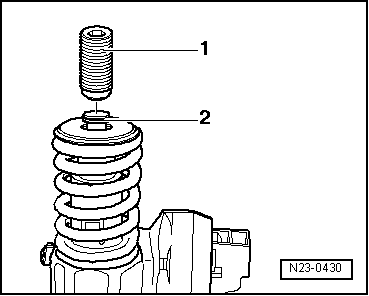
–  Before fitting the injector pump, check that the 3 O-rings, the thermal protection joint and securing are seated correctly.
  Note
The O-rings must not be twisted.
–  Oil all of the O-rings and fit the injector pump very carefully into its allotment on the cylinder head.
–  Press evenly, insert the injection pump to the limit of its allotment on the cylinder head.
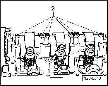
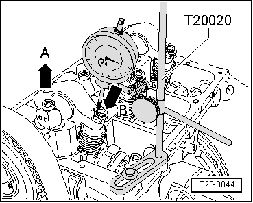
–  Fit the attachment stopper into the lateral groove of the injection pump.
  Note
If the injection pump is not perpendicular to the attachment stopper, the attachment bolt may come out. Due to this fact, damage may occur to the injection pump and the cylinder head.
–  To avoid this the injection pump must be placed as follows:
–  Screw in the new attachment bolt in the attachment block to the point where the injection pump may still rotate a little.
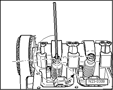
–  Place the injection pump so that it is perpendicular to the allotments for the camshaft.
  Note
There are two models of injection pump. One of them is equipped with a nut for the larger electronic valve. For this reason, follow the specific instructions for each one of these as follows:
Injection pump with larger electronic valve nut
  N23-0319
–  Insert the measuring tool -T20110B- by the larger end and move the injector pump until the cylindrical part of the injector nut touches the centring device.
Injection pump with smaller electronic valve nut
–  Insert the measuring tool -T20110B- by the smaller end and move the injector pump until the cylindrical part of the injector nut touches the centring device.
All:
–  If necessary, readjust the injector pump unit and tighten the securing bolt for the attachment block as follows:
t  Tightening torque: 12 Nm +270° (3/4 rotation).
–  Fit the rocker axle and tighten the new attachment bolts as described below.
–  Tighten, respectively, first the interior bolts and the exterior bolts in various steps.
t  Tightening torque: 20 Nm 90° (1/4 rotation).
  E23-0092
–  Position a dial gauge on the adjuster screw of the injector-pump unit as shown.
–  Rotate the crankshaft in the normal engine direction of rotation until the roller of the rocker lever is on the point of the operation cam.
t  The roller side -arrow A- is at the highest point; the gauge -arrow B- is at the lowest point
–  Remove the gauge.
–  Screw in the adjustment bolt on to the rocker 4 Nm (the injector pump is at the limit).
  E23-0044
–  Screw out the adjustment screw from the end by 225°.
–  Maintain the adjustment bolt in this position and tighten the counter nut to a torque of 30 Nm.
–  Connect the injector pump connection and fit the cylinder head cover with the notched belt → Chapter.
  N23-0309

Engine control unit > < O-rings for the injection pump: removing and fitting