
Leon Mk1
| Engine: dismounting |

| Special tools and workshop equipment required |
| t | Hose clamps -3094-, see equivalent → Anchor |
| t | Torque wrench -V.A.G 1331-, see equivalent → Anchor. |
| t | Torque wrench -V.A.G 1332-, see equivalent → Anchor. |
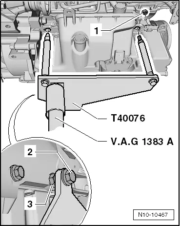
| t | Engine/gearbox crane -V.A.G 1383 A-, see equivalent → Anchor |
| t | Stepladder -VAS 5085-, see equivalent → Anchor |
| t | Engine bracket -T40076-, see equivalent → Anchor |

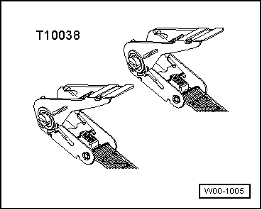
| t | Transport lock for the decoupling element -T10403-, see equivalent → Anchor |
| t | Torque wrench -V.A.G 1332-, see equivalent → Anchor. |
| t | Engine sealing plug set -VAS 6122-, see equivalent → Anchor |
| t | Collector tray for workshop crane -VAS 6208-, see equivalent → Anchor |
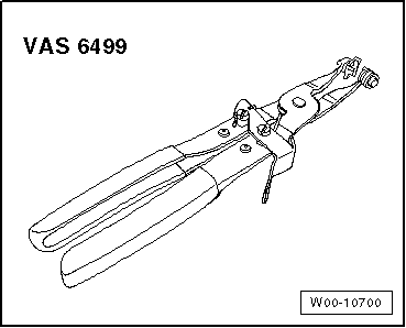
| t | Hose clamp pliers -VAS 6340-, see equivalent → Anchor |
| t | Grease (vehicles with manual gearbox) -G 000 100- |
| t | Cable tie |
|
|
 Note
Note
|
|
 WARNING
|
|
|
|
Note
|
|
|
|
|
|
|
|
|
|
|
|
|
|
|
|
|
|
Note
|
|
|
|
|
|
|
|
|
|
|
|
|
|
|
|
|
|
|
|
|
|
|
|
|
|
|
|
|
|
|
|
|
|
|
|
 Caution
|
|
Note
|
|
|
|
|
|
|
|
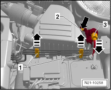
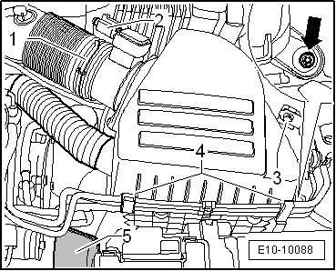
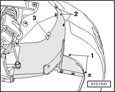
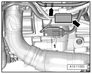
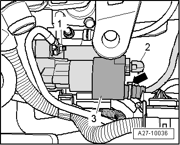
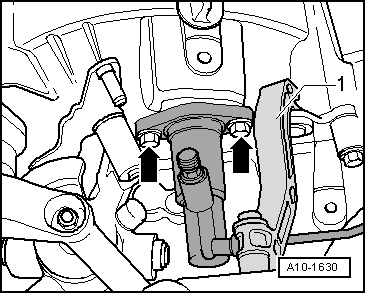
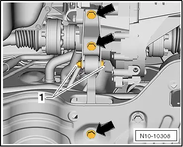
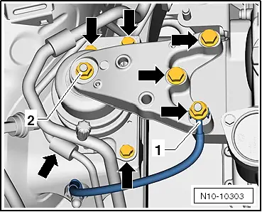
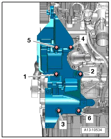
| 1. | Remove the fixing bracket -1- between the particle filter and the exhaust gas turbocharger. | |
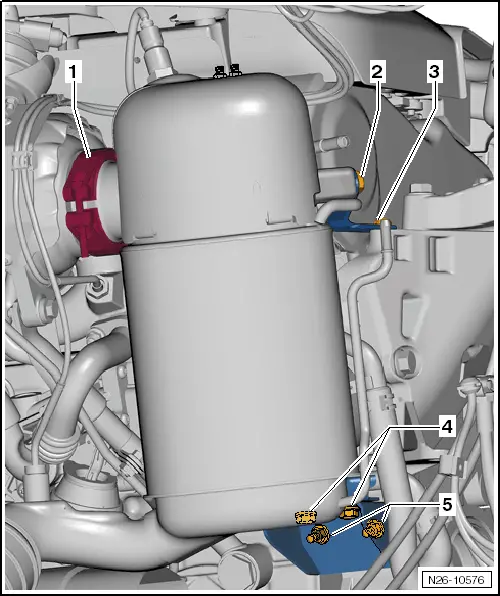
| 2. | Remove bolts -2 ... 3-. | |
| 3. | Remove bolts -4-. | |
| 4. | Unscrew nuts -5- | |
Note
|
|
|
|
|
Note
|
|
|
|
|
|
|
|
Note
|
|
Note
|
|
|
|