
Leon Mk1
|
|
|
|
|
|
|
|
|
 Note
Note
|
|
|
|
|
|
|
|
|
|
|
|
|
|
|
|
|
|
 Caution
|
|
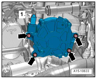
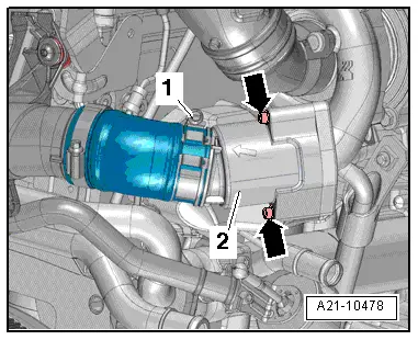
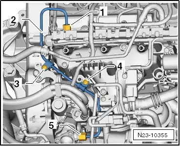
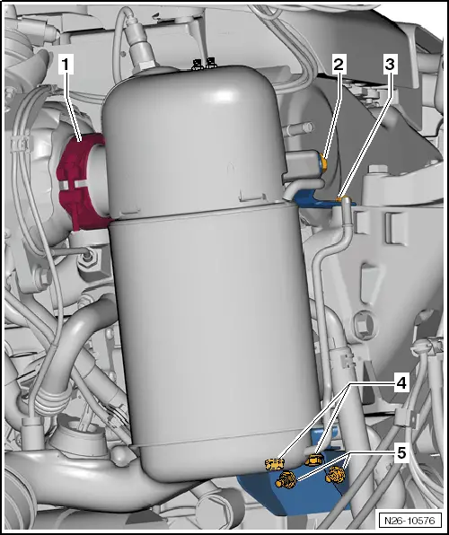
| 1. | Remove securing clamp between particulate filter and turbocharger | |
| 2. | Unscrew bolts and nuts -2 … 3- | |
| 3. | Remove bolts -4-. | |
| 4. | Unscrew nuts -5- | |
|
|
|
|
|
|
|
|
|
Note
|
|
|
|
|
|
Note
|
|