seat Workshop Repair Guides

SEAT Workshop Service and Repair Manuals

Removing and installing exhauster pump > < Removal:
Installation
Installation
  Note
t  Always renew cylinder head bolts.
t  In cases of repair, carefully remove gasket remains from cylinder head and cylinder block. Ensure that no long scores or scratches are made on the surfaces. When using abrasive paper do not use a grade less than 100.
t  Carefully remove emery and abrasive remains.
t  Do not remove new cylinder head gasket from packaging until it is ready to be fitted.
t  Handle gasket very carefully. Damaging the silicone layer or the indented area will lead to leaks.
t  Proceed with extreme caution. Use a further mechanic to provide assistance.
t  Thread cylinder head into toothed belt guard.
   
t  When doing this, cylinder head must not scrape over dowel sleeves -A-.
–  Before fitting cylinder head, remove crankshaft stop -T10050- and turn crankshaft opposite direction of rotation until all pistons are nearly uniformly below TDC.
  N15-10645
–  Note cylinder head gasket identification:
1 - Part number
2 - Holes
3 - Disregard
–  Fit cylinder head gasket with marking facing upwards.
  N15-10581
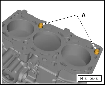
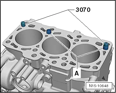
–  To centralise, screw guide pins -3070/9- into outer holes on inlet side.
  Note
t  
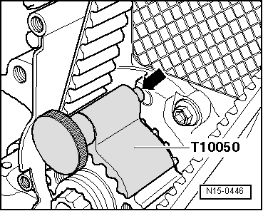
Position tensioning roller on studs when fitting cylinder head.
t  
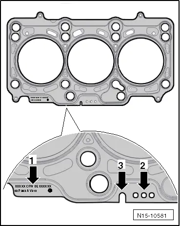
If the cylinder head gasket or cylinder head have been replaced, select the new cylinder head gasket according to the number of holes on the old cylinder head gasket.
t  If parts of the crankshaft assembly have been renewed, the new cylinder head gasket must be selected by measuring the piston projection at „TDC“ → Chapter.
–  Fit cylinder head.
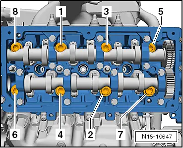
–  Screw in 8 cylinder head bolts by hand until they make contact.
–  Unscrew guide pins -3070/9- through bolt holes in cylinder head and screw in remaining cylinder head bolts by hand until they make contact.
  N15-10648
–  Tighten cylinder head in 4 stages in sequence shown as follows:
1 - Tighten initially with torque wrench:
Stage I = 35 Nm
Stage II = 50 Nm
2 - Turn further with rigid spanner:
Stage III = turn 90° further
Stage IV = turn 90° further.
–  Secure rear toothed belt guard on cylinder head.
–  Attach the hub and the camshaft sprocket.
–  Lock camshaft and high-pressure pump with diesel injection pump locking pin -3359-
  N15-10647
–  Turn crankshaft to TDC for Nr. 1 cylinder in engine direction of rotation and lock crankshaft crankshaft stop -T10050-.
Remaining assembly is performed in reverse sequence. Note the following:
–  Re-install toothed belt → Chapter.
–  Install cylinder head cover → Chapter.
–  Install oil supply line and turbocharger support → Chapter
–  Install poly V-belt → Chapter.
–  Fill up with coolant → Chapter.
–  Top up engine oil → Chapter.
After any work on the fuel system
Connect a vehicle diagnosis tester.
Perform the function „Filling/bleeding high pressure pump/fuel system“ in „Guided functions“ → Chapter.
–  Carry out road test and read fault memories → Chapter.
  N15-0446

Removing and installing exhauster pump > < Removal: