seat Workshop Repair Guides

SEAT Workshop Service and Repair Manuals

Removing and installing cylinder head > < Removal:
Fitting (adjusting the valve timing)
  Note
t  The toothed belt may only be adjusted on cold engines, as the indicator position on the tensioning element varies depending on the engine temperature.
t  If the tensioning roller is to be renewed, the engine bracket must be removed → Chapter.
t  Renew securing bolts for camshaft pulley and high-pressure pump pulley.
   
l  Tensioning roller must be locked with locking tool -T10265- and secured to right stop.
  N15-10333
l  Crankshaft is locked using crankshaft stop -T10050-.
  Note
Turn camshaft hub with counter-hold tool -T10172- and adapters -T10172/4- until camshaft can be locked in position. Hand-tighten at least one securing bolt -1- before performing the above mentioned procedure.
  A13-0350
–  Lock the camshaft using the locking pin -3359-. To do this, insert locking pin through outer free elongated hole into hole in cylinder head.
  N15-10423
–  Loosen the hand-tightened bolt again.
Bolts -arrows- are fitted but not tightened.
It should just be possible to turn the sprocket on the camshaft without axial movement.
  Note
If necessary, turn hub of high-pressure pump at bolt heads with screwdriver until it can be locked in position.
  A15-10798
Positioning hub of high-pressure pump
  N15-10427
–  Lock the camshaft hub with locking pin -3359-. To do this, push locking pin into adjustment hole outside toothed belt pulley.
Bolts -1- are fitted but not tightened.
The high-pressure pump sprocket should still just turn, but there must be no axial movement.
–  Turn camshaft sprocket and toothed belt sprocket of high-pressure pump in their elongated holes clockwise to stop.
  A13-10615
–  Fit toothed belt in sequence described:
1 - Crankshaft sprocket
2 - Tensioning roller
3 - Camshaft sprocket
4 - Coolant pump sprocket
5 - High-pressure pump sprocket
6 - Idler roller
–  Unscrew the securing nut of the tensioning roller and remove the Locking tool -T10265-.
  Note
  A13-10540
Ensure that belt tensioner seats correctly in rear toothed belt guard -arrow-.
  N15-10424
–  Carefully turn the eccentric adjuster of the belt tensioner clockwise using an angle screwdriver -T10264-. Indicator -2- must be roughly past the centre of the gap in the base plate (rectifies itself during pretensioning).
Ensure that the securing nut -1- does not turn as well.
–  Hold belt tensioner in this position. Tighten the tension pulley fixing nut as follows: 20 Nm and turn 45° further
  N15-10334
–  Fit counter-hold tool -T10172- as shown. Press counter-hold tool -T10172- in direction of arrow and keep camshaft sprocket in pretensioning position.
–  In this position, first tighten the securing bolts -1- of the camshaft sprocket and the toothed belt sprocket of the high pressure pump manually and then to 20 Nm.
–  Remove locking pins -3359- and crankshaft stop -T10050-.
–  Turn crankshaft at least two rotations in engine direction of rotation and set to just before TDC No. 1 cylinder.
–  Place crankshaft stop -T10050- on the crankshaft's toothed belt sprocket again.
  N15-10423
–  Now turn crankshaft in engine direction of rotation until crankshaft stop pin -arrow- engages in sealing flange whilst turning.
  Note
  N15-0446
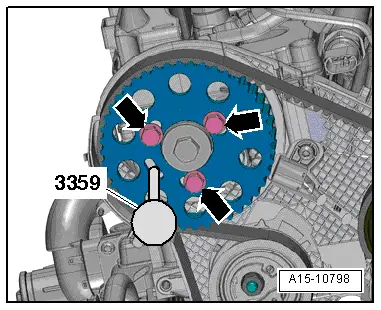
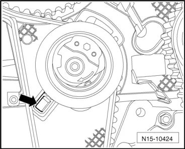
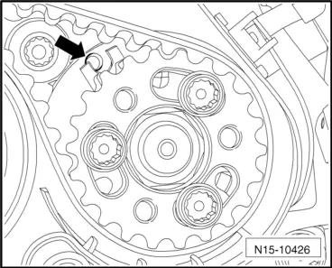
During the following check, only the camshaft and the crankshaft are locked. It is very difficult to find the securing position of the high-pressure pump hub again. However, a slight deviation -arrow- does not influence the engine operation.
–  Check whether:
t  
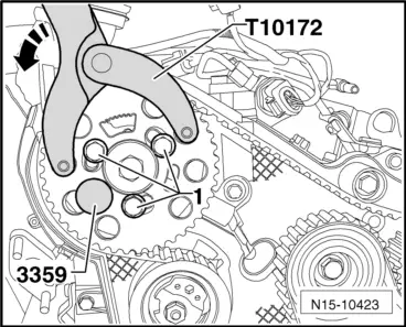
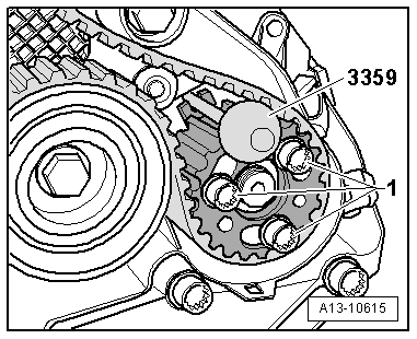
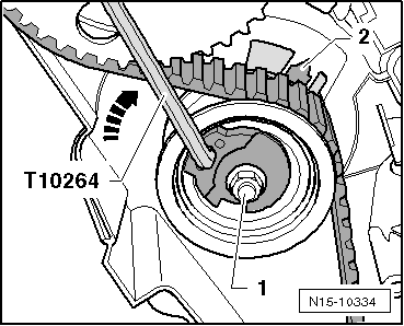
Camshaft hub can be locked with locking pin -3359-.
t  Tensioner lug is centred or a max. of 5 mm to the right of the slot on the base plate.
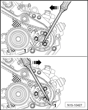
If hub on camshaft cannot be locked:
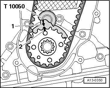
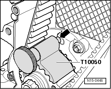
–  Pull crankshaft stop -T10050- back until pin uncovers hole.
–  Turn crankshaft out slightly past TDC by turning it in the opposite direction of engine rotation.
–  Now turn crankshaft slowly in direction of engine rotation until camshaft hub can be secured in position.
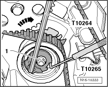
–  After locking, loosen securing bolts of crankshaft toothed belt sprocket.
If pin of crankshaft stop -T10050- is on left side of bore:
  N15-10426
–  Turn crankshaft in engine direction of rotation until crankshaft stop pin engages in sealing flange whilst turning.
–  Tighten securing bolts of camshaft toothed belt sprocket hand-tight at first and then to 20 Nm.
If pin of crankshaft stop -T10050- is on right side of bore:
–  Turn crankshaft slightly counter to engine direction of rotation again.
–  Turn crankshaft in engine direction of rotation until crankshaft stop pin arrow engages in sealing flange whilst turning.
–  Tighten securing bolts of camshaft toothed belt sprocket hand-tight at first and then to 20 Nm.
Continuation
–  Remove locking pin -3359- and crankshaft stop -T10050-.
–  Turn crankshaft at least two rotations in engine direction of rotation and set to just before TDC No. 1 cylinder.
–  Repeat check.
–  If camshaft hub can be secured in position, tighten securing bolts as follows:
  N15-0446
t  Camshaft gear: Turn 45° further. Counterhold using counterhold tool -T10172- and adapters -T10172/4-.
–  Install middle and lower toothed belt guards.
–  Fit the vibration damper/pulley: Tightening torque: 10 Nm + turn 90° further
–  Install poly V-belt → Chapter.
–  Install upper toothed belt guard.
Further assembly is basically the reverse of the dismantling sequence. Note the following:
t  Ensure that fuel hose connections are tight.
t  Do not interchange supply line and return line (return line blue or with blue marking, supply line white).
–  Mount the wheel housing moulding.
–  Install noise insulation → General body repairs, exterior; Rep. gr.50.
  N15-10423

Removing and installing cylinder head > < Removal: