seat Workshop Repair Guides

SEAT Workshop Service and Repair Manuals

Fitting (adjusting the valve timing) > < Removing, installing and tensioning toothed belts
Removal:
Removal:
»Carry out the following work sequence«
  Note
t  Engine bracket must be removed to exchange belt tensioner.
t  The engine bracket must be loosened only when the assembly mounting has been removed.
t  The assembly mounting may only be removed if the engine is supported with support bracket -10-222A-!
t  Engine support: Removing → Chapter.
t  
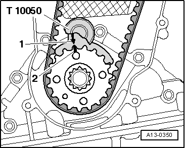
Adjustment work on toothed belts must be performed only on cold engines, as the indicator position on the tensioning element varies depending on the engine temperature.
–  Remove engine cover → Chapter
–  With the ignition switched off, disconnect battery → Electrical system; Rep. gr.27
–  Remove noise insulation → General body repairs, exterior; Rep. gr.50.
–  Remove charge air pipe »cold« side → Chapter.
–  Remove poly V-belt → Chapter.
   
–  Remove upper toothed belt cover, release clips -arrows- for this purpose.
  A10-11056
–  Unscrew the -fixing elements 1 ... 3- of the right and left soundproofing.
  A10-1643
–  Remove bolts -arrows-.
–  Press coolant lines aside slightly.
–  Remove vibration damper → Chapter.
  N21-10321
–  Remove bolts -arrows-.
–  Remove toothed belt guard downwards.
  Note
t  Engine bracket must be removed to exchange belt tensioner.
t  The engine bracket must be loosened only when the assembly mounting has been removed.
t  The assembly mounting may only be removed if the engine is supported with support bracket -10-222A-!
t  Remove engine bracket → Chapter.
  N13-10350
–  Turn engine to TDC and lock crankshaft toothed belt pulley in position with crankshaft stop -T10050-. Fit the crankshaft stop in the teeth from the face side of the toothed belt pulley.
l  The mark -2- on the toothed pulley and the arrow -1- on the crankshaft stop -T10050- must align -arrow-. The pin of the crankshaft stop must engage in the aperture in the sealing flange.
  A13-0350
The arrow on the camshaft pulley must be at almost »12 o'clock«.
–  Mark the toothed belt D.O.R.
  N15-10498
–  Loosen bolts -arrows- approx. 90° for camshaft toothed belt pulley.
  A15-10798
–  Using bit XZN 10 -T10385-, loosen bolts -1- for high-pressure pump sprocket approx. 90°.
  N23-10357
–  Unscrew the securing nut of the tensioning roller -1- and turn the eccentric adjuster of the tensioning roller with the wrench -T10264- anti-clockwise -Arrow- until the tensioning roller can be locked with the Locking pin -T10265-.
  N15-10332
–  Turn belt tensioner eccentric clockwise -arrow- to stop. Tighten securing nut -1- hand-tight.
  Caution
Risk of damage to the timing belt when the direction of rotation is reversed compared to the previous operation.
Before removing, mark direction of rotation of toothed belt with chalk or felt-tip pen for re-installation.
–  Take off toothed belt first from idler roller and then from remaining sprockets.
  N15-10333

Fitting (adjusting the valve timing) > < Removing, installing and tensioning toothed belts