
Leon Mk1
|
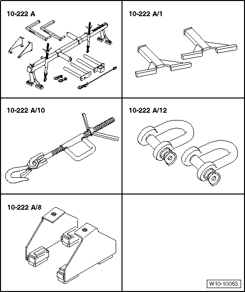
| Special tools and workshop equipment required |
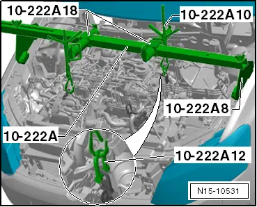
| t | Suspension tool -10-222 A-, see equivalent → Anchor |
| t | Frame -10 222A/1-, see equivalent → Anchor |
| t | Additional hook -10-222 A/10-, see equivalent → Anchor |
| t | Shackle -10-222 A/12-, see equivalent → Anchor. |
| t | Adapter -10 - 222 A /8-, see equivalent → Anchor |
|
|
|
|
 Note
Note
|
|
|
|
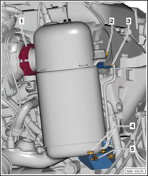
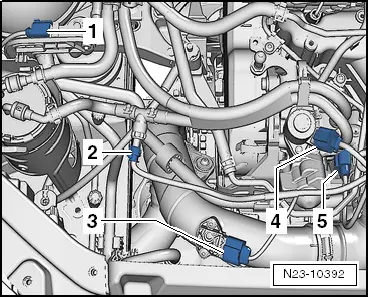
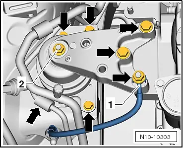
| 1. | Unscrew bolts -2 + 3-. | |
| 2. | Removing the top bracket of the particle filter. | |
| 3. | Unscrew bolts + nuts - 4 + 5- | |
| 4. | Removing the bottom bracket of the particle filter. | |
|
Note
|
|
|
|
Note
|
|
Note
|
|
 Caution
|
|
 WARNING
|
|