
Leon Mk1
| Piston and conrod - assembly overview |
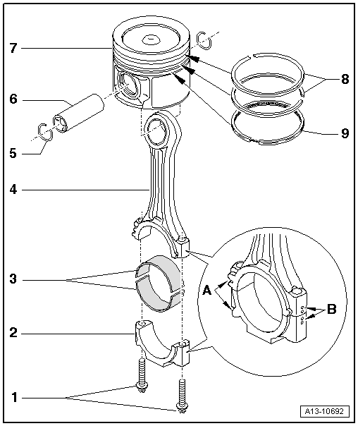
| 1 - | Bolt. |
| q | Replace |
| q | Oil threads and contact surface. |
| q | 30 Nm + turn +90° further |
| 2 - | Conrod bearing cap |
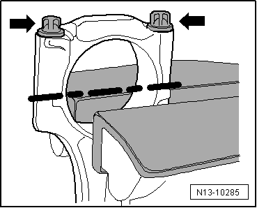
| q | Due to the cracking method used to separate the bearing cap from the conrod in manufacture, the caps only fit in one position and only on the appropriate conrod |
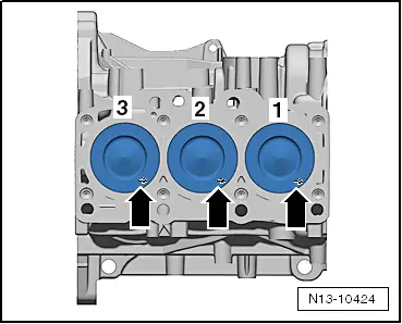
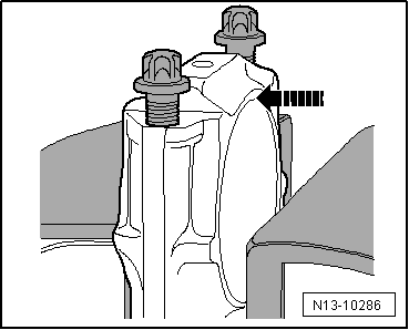
| q | Mark cylinder allocation in colour -B- |
| q | Fitting position: Marking -A- towards the pulley end |
| 3 - | Bearing cap |
| q | Installation position → Fig. |
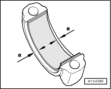
| q | Mark used bearing shells for re-installation but not on bearing surface |
| q | Renew bearing shells worn down to base layer. |
| q | Note design: Upper bearing shell (towards piston) made of wear-resistant material. Distinguishing feature of new bearing shells: Black line on contact surface in area of joint |
| q | Check for secure seating. |
| 4 - | Conrod |
| q | Renew as set only. |
| q | With industrially cracked conrod bearing cap |
| q | Separating parts of new conrod → Fig. |
| q | Mark cylinder allocation in colour -B- |
| q | Fitting position: Marking -A- towards the pulley end |
| q | Axial clearance: Wear limit: 0.37 mm |
| q | Measuring radial clearance → Chapter |
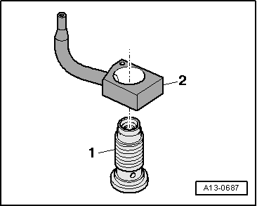
| 5 - | Circlip |
| q | Replace |
| 6 - | Piston pin |
| q | If difficult to remove, heat piston to approx. 60 °C |
| q | Remove and install with drift -VW 222 A- |
| 7 - | Piston |
| q | with combustion chamber |
| q | Mark installation position and cylinder number → Fig. |
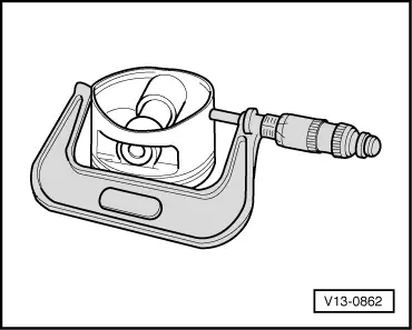
| q | check → Fig. |
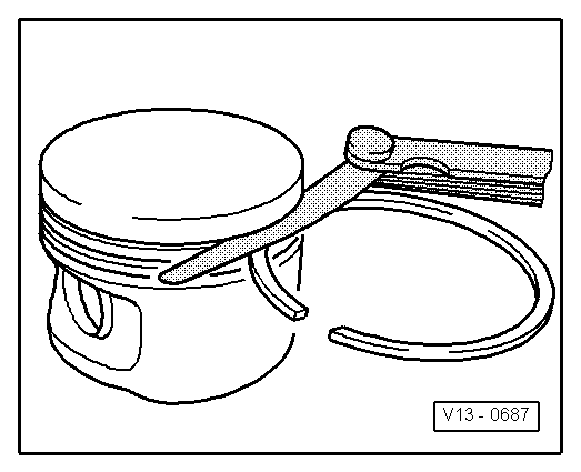
| q | Install using piston ring clamp |
| q | Piston and cylinder dimensions → Chapter |
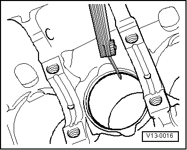
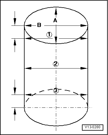
| q | Measuring cylinder bore → Fig. |
| q | Measuring piston projection at „TDC“ → Chapter |
| 8 - | Piston rings |
| q | Compression rings |
| q | Offset gaps by 120° |
| q | Use piston ring pliers to remove and install |
| q | Fitting position: Marking „TOP“ or side with lettering faces towards piston crown |
| q | Measuring piston ring gap → Fig. |
| q | Measuring axial clearance → Fig. |
| 9 - | Piston ring |
| q | Oil scraping ring |
| q | Offset gap 120° from bottom compression ring |
| q | Use piston ring pliers to remove and install |
| q | Measuring piston ring gap → Fig. |
| q | Measuring axial clearance → Fig. |
| Piston ring | new mm | Wear limit mm |
| 1. compression ring | 0,20 … 0,40 | 1,00 |
| 2. compression ring | 0,20 … 0,40 | 1,00 |
| Oil scraping ring | 0,25 … 0,50 | 1,00 |
|
|
| Piston ring | new mm | Wear limit mm |
| 1. compression ring | 0,06 … 0,09 | 0,25 |
| 2. compression ring | 0,05 … 0,08 | 0,25 |
| Oil scraping ring | 0,03 … 0,06 | 0,15 |
 Note
Note
|
|
|
|
|
|
|
|
|
|
|
|
Note
|
|