seat Workshop Repair Guides

SEAT Workshop Service and Repair Manuals

Ignition system, glow plug system > < Nozzle units / high-pressure reservoir
Removal:
Removal:
»Carry out the following work sequence«
   
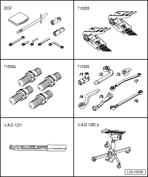
Special tools and workshop equipment required
t  Box wrench set for lambda probe -3337-, see equivalent → Anchor
t  Tension belt -T00038-, see equivalent → Anchor
t  Adjustment tool -T10096-, please see Correspondence → Anchor
t  Adjustment tool -T10395-, see equivalent → Anchor
t  Torque wrench -V.A.G 1331-, see equivalent → Anchor.
t  Engine/gearbox crane -VAG 1383A-, see equivalent → Anchor

   
t  Retainer (transport lock) -T10403-
Removal:
–  Turn wheels to straight ahead position.
–  Loosen universal joint → Running gear, axles, steering; Rep. gr.48.
  W00-10761
–  To do this, remove cover -2- and unscrew plastic nuts -1-.
  S48-0106
–  Unscrew bolt -1- from universal joint and pull universal joint off in direction of arrow.
–  Remove engine cover panel → Chapter.
  S48-0107
–  Disconnect connectors -1- for exhaust temperature sender 1 -G235-.
–  Disconnect connectors -2- for Lambda probe -G39-.
  N26-10521
–  Unscrew Lambda probe -G39--1- using Lambda probe open ring spanner set -3337-.
–  Remove securing clamp -2- between catalytic converter with non-engine-mounted particulate filter and turbocharger.
–  Remove noise insulation → General body repairs, exterior; Rep. gr.50
  N26-10516
–  Disconnect connector -2- to pressure differential sender -G505-.
–  Unscrew pressure differential sender -G505--1-.
–  Disconnect connector -3- to pressure differential sender -G505-.
–  Pull lines from retainers, remove cable ties if necessary.
The flexible joint in the front exhaust pipe must not be bent more than 10° - otherwise it can be damaged.
  N26-10515
If the catalytic converter with non-engine-mounted particulate filter is to be re-installed, a transportation sleeve -arrow- must always be secured to the flexible joint in front exhaust pipe.
  N26-10517
–  Open bracket -B- of hydraulic lines -A-.
  N26-10318
–  Remove pendulum support -arrows-.
Item -1- must not be loosened.
–  Place engine and gearbox jack -VAG 1383A- under subframe.
–  Unscrew the bolts of the engine assembly one after another and replace them with the fixing bolts → Running gear, axles, steering; Rep. gr.40.
–  Loosen anti-roll bar at top of coupling rod → Running gear, axles, steering; Rep. gr.40.
–  Carefully lower subframe with engine and gearbox jack -VAG 1383A- leaving the steering on subframe in the process.
The hydraulic steering circuit does not need to be opened for this → Running gear, axles, steering; Rep. gr.40.
–  Lower on the right side max. 10 cm -movement arrow-.
  N10-10308
–  To prevent the hydraulic lines being overstretched, lower on the left side max. 7 cm.
  Note
Secure subframe with steering box to underside of vehicle with belt -T00038-.
  N26-10346
–  Remove securing bolts -1- and remove cover from cylinder block for right drive shaft.
–  Unscrew exhaust gas temperature sender 3 -G495- using -T10395/6- → Item from front exhaust pipe.
  N17-10184
–  Remove right underbody panelling → General body repairs, exterior; Rep. gr.66.
  N26-10520
–  Remove cover from connector for exhaust temperature sender 4 -G648-.
  N26-10524
–  Disconnect connector for exhaust temperature sender 4 -G648-.
  N00-10683
–  Unscrew bolts -1- and then nuts -2-.
–  Remove particulate filter bracket.
  Note
The flexible joint in the front exhaust pipe must not be bent more than 10° - otherwise it can be damaged.
  N26-10535
If the particulate filter is to be re-installed, a transportation sleeve -arrow- must always be secured to the flexible joint in front exhaust pipe.
  N26-10517
–  Loosen securing bolts -arrows- of clamping sleeve, then push down backwards from front exhaust pipe.
–  Detach front exhaust pipe from mounting brackets.
Carefully remove the particle filter with the pressure differential sender -G505- taking them out via the lowered subframe in the process.
  V26-0733
–  Remove catalytic converter with non-engine-mounted particulate filter by turning 180° around its own axis.
  A26-10712

Ignition system, glow plug system > < Nozzle units / high-pressure reservoir