seat Workshop Repair Guides

SEAT Workshop Service and Repair Manuals

Cylinder head - Assembly overview > < Valve control
Removing and installing camshaft housing
t  Removing → Anchor
t  Remove the rear silencer → Anchor
t  Install camshafts → Anchor.
t  Installing → Anchor
Consult the equivalence table for tools and equipment according to applicability among Seat / VW / Audi / Skoda → Chapter.
   
Special tools and workshop equipment required
t  Torque wrench (40... 200 Nm) -V.A.G 1332-, see equivalent → Anchor
t  Torque wrench (5... 50 Nm) -V.A.G 1331-, see equivalent → Anchor
t  Base -VAS 6340-, see equivalent → Anchor
t  Hose clamp -T10172-, see equivalent → Anchor
t  Hose clamp -3415-, see equivalent → Anchor
t  Interlocking mandril -3415/1-, see equivalent → Anchor

   
t  Camshaft clamp -T10123-
  W00-1235
t  Fastening bolt -T10121-
t  Two studs (M 6 x 80)
Removing
  Note
t  In this engine the camshafts are housed in a casing. Therefore, the camshaft housing can only be removed after removing the distribution casing.
t  The camshaft housing sealing surface must not be reworked.
  W00-1233
–  With ignition switched off, disconnect earth wire -arrow- at battery.
  A10-1612
–  Unplug connector -1- from Hall sender -G40-.
–  Unlock the engine cover -arrows- and pull upwards.
–  Unscrew earth cable from camshaft housing.
  N13-10290
–  Remove the ignition coils with output stages → Chapter.
–  Remove cable guide with wiring harness from camshaft housing.
–  Remove the coolant bleeding tube from the camshaft housing.
–  Remove the cable harness support → Item.
–  Remove valve timing housing → Chapter.
–  Remove distribution chain → Chapter.
  N28-10066
–  Loosen camshaft housing bolts from outside to inside, alternately and diagonally and remove.
–  Carefully lift camshaft housing off.
  N15-0540
Remove camshafts
–  Loosen the bolts on the camshaft casing in the order shown and remove.
–  Carefully lift camshaft housing off.
Fit the camshafts
  Note
The projection of the intake camshaft should be above the drill hole for the Hall sensor.
  N15-0612
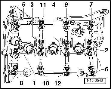
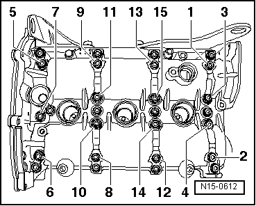
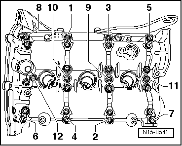
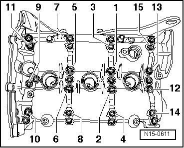
–  Manually tighten the camshaft bearing bolts in the sequence indicated.
Take care not to tilt the camshaft bearing caps. Tightening torque: 10 Nm +1/4 turn further (90º)
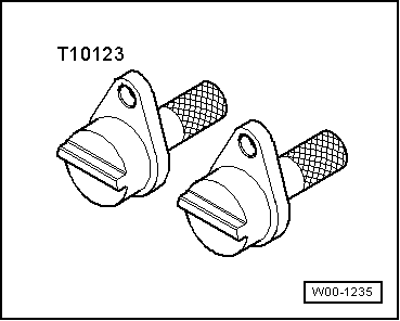
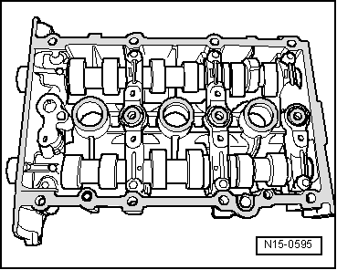
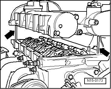
Installing
  Caution
The studs (M6x80) must be screwed into cylinder head before installing camshaft housing.
The camshaft housing is guided by the studs, so that the roller rocker fingers do not slip off the supporting elements.
Install in reverse order to dismantling, noting the following:
Requirements:
l  Pistons must not be at TDC.
  Note
On turning the camshafts, the valves may hit the pistons if they are at TDC.
–  Remove sealant remnants on cylinder head and camshaft housing with a commercially available sealant remover.
–  Also prevent dirt and residual sealant from entering cylinder head.
–  Clean sealing surfaces. They must be free of oil and grease.
  N15-0611
–  Apply thin, even coat of sealant on clean camshaft housing sealing surface. See hatched area in illustration.
  Note
The sealant must not be applied too thickly otherwise excess sealant could enter the oil channels and cause damage to the engine.
  N15-0595
–  Ensure that all roller rocker fingers contact valve stem ends -1- correctly and that they are clipped into their respective support elements -2-.
–  Bolt two studs (M6 x 80) on the cylinder head before fitting the camshaft housing.
  N15-0076
–  Carefully fit the camshaft housing vertically onto the cylinder head studs and dowel pins -arrows-.
  N15-0173
–  Evenly tighten new camshaft housing securing bolts from inside to outside alternately and diagonally.
Ensure that camshaft housing is not canted. Tightening torque: 10 Nm +1/4 turn further (90°).
  Note
After installing the camshaft housing, wait about 30 minutes for the sealant to dry.
  N15-0541

Cylinder head - Assembly overview > < Valve control