seat Workshop Repair Guides

SEAT Workshop Service and Repair Manuals

Exhaust system > < Servicing injection system
Checking injectors
Checking injectors
t  Jet projection image and seal: checking → Anchor
t  Check the fuel injection quantity → Anchor
Consult the equivalence table for tools and equipment according to applicability among Seat / VW / Audi / Skoda → Chapter.
   
Special tools and workshop equipment required
t  Torque wrench (5... 50 Nm) -V.A.G 1331-, see equivalent → Anchor
t  Remote control -V.A.G 1348/3A-, please see Correspondence → Anchor
t  Adapter cable -V.A.G 1348/3-2-
t  Auxiliary cable kit -VAG 1594C-
t  Injection rate tester -V.A.G 1602-
t 

  WARNING
Fuel system is under pressure! Wear eye protection and gloves to avoid injuries and skin contact. Before opening the system place a cloth around the connection. Then release pressure by carefully pulling fuel hose from connection.
Test condition
l  The fuel pressure must be okay.
l  Engine and fuel temperature approx. 20 C.
Checking sequence
–  Take out air cleaner casing.
  W00-0596
–  Remove the 2-pin connector from the coolant temperature sensor -G62--arrow-.
–  Disconnect the plug from the ignition coils → Chapter.
–  Detach hose from support -1-.
–  Open support -2- and unclip hoses.
  N24-10590
–  Remove the hose from the fastenings -3-.
–  Pull off connector -4-.
–  Unplug connectors -6- from injectors.
–  Remove bolts -5-.
–  Remove the fuel rail together with the injectors -7- from the intake manifold holder.
Check the jet projection image and tightness
The fuel hoses must remain connected. Leave the fuel rail loose in the intake manifold so that no dirt can enter the intake line.
  N24-1679
–  Connect the digital potentiometer -V.A.G 1630- to both contacts of the connector using auxiliary cables and adjust the side connected to 15 kΩ.
–  Place a container under the injector to be checked and pull connectors off all other injectors.
–  Operate the starter with the aid of a second person.
Injector must spray in pulses.
–  Repeat the check on all other injectors.
  S24-0342
In the process, take care that only the valve to be checked is connected.
–  Then check the tightness of the injectors.
No more than 2 drops/min may leak out.
If the fuel loss is greater:
–  Turn the ignition off.
–  Renew defective injector → Chapter.
Check the fuel injection quantity
  Note
t  When checking the injection quantity, also check the spray pattern.
t  The shape of the spray pattern should be the same for all valves.
–  Insert injector to be checked into measuring beaker.
  S24-0498
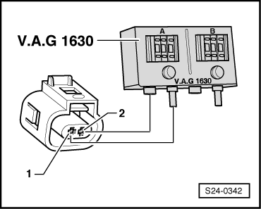
–  Connect a contact of the valve to the earth terminal of the battery.
–  Then connect the second contact of injector to the remote control.
–  Connect the clamp to the positive (+) pole of the battery.
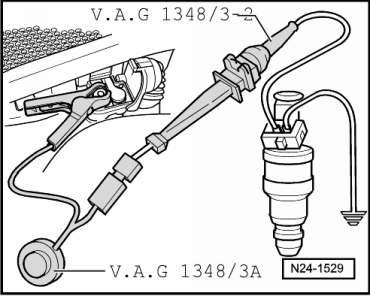
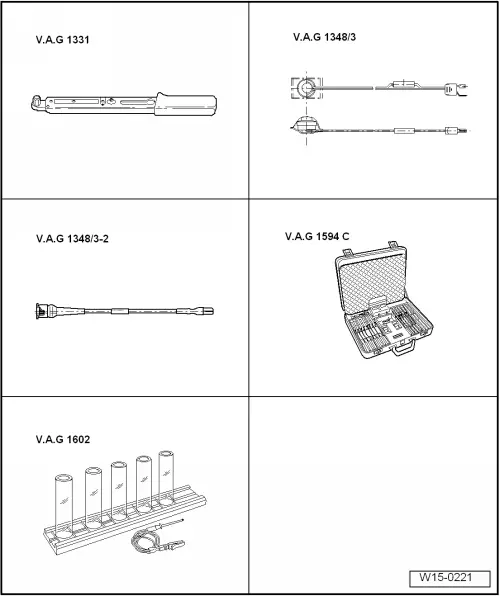
–  To protect the battery positive (+) and fuse holder, connect using the test lead and adapter cable -V.A.G 1348/3-2-.
The fuel supply unit must run.
–  Activate remote control for 30 seconds.
–  Repeat the check on all other injectors. Always use a new measuring container.
–  Once all injectors have been actuated, place the measuring container on a flat surface.
–  Disconnect the voltage supply of the fuel delivery unit.
–  Compare the injected quantities.
Specification:
Specification: 85 ... 91 ml per injector.
If the measured values of one or more injectors are above or below the prescribed specifications:
–  Renew defective injector → Chapter.
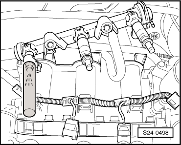
Fit the injectors in the reverse order of removal. Note the following:
t  Renew O-rings on all injectors and lightly moisten with clean engine oil.
t  Fit fuel rail with secured injectors onto intake manifold and press in evenly.
Tightening torque: 10 Nm
  N24-1529

Exhaust system > < Servicing injection system