seat Workshop Repair Guides

SEAT Workshop Service and Repair Manuals

Distribution timing: adjustment > < Removing and installing toothed belt
Checking distribution timing
Special tools and workshop equipment required
   
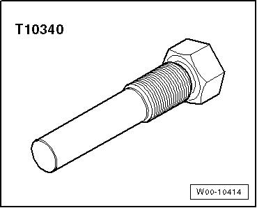
t  Locating bolt -T10340-
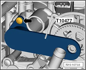
t  Camshaft clamp -T10477-
Checking sequence
  W00-10414
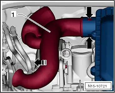
–  Press locking lugs -arrows- and pull intake connection off -1- in -direction of arrow-.
–  Disconnect hose -1- at air cleaner housing.
  N15-10721
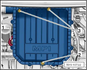
–  Pull air filter housing upwards off studs at positions -2- and -3-.
  N15-10722
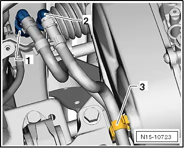
–  Unlock and disconnect fuel supply line -1- and breather line -2-. → Fuel supply system - Petrol engines; Rep. gr.20.
–  Open line guide -3- and detach hoses.
–  Seal lines so that fuel system is not contaminated by dirt.
–  Detach clamps -arrows-.
  N15-10723
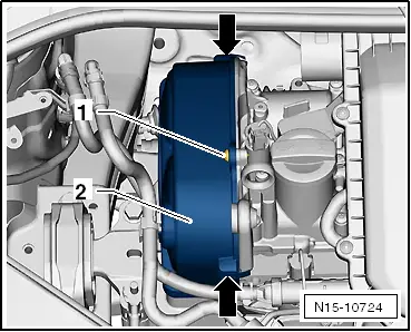
–  Unscrew securing bolt -1- and remove cover -2-.
–  Undo and remove bolts -arrows-.
  N15-10724
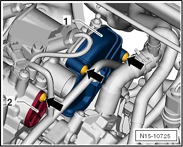
–  Unclip duct from the guard.
–  Remove cover -1- and cover -2-.
  N15-10725
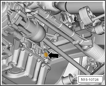
–  Unscrew plug -arrow- from crankcase.
–  Lower lifting platform completely.
  Note
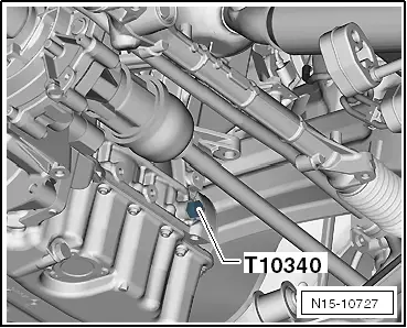
t  The lifting platform must be lowered completely in order to allow for screwing the locking pin -T10340- into the crankcase.
t  When the vehicle is raised, the hole is hidden behind the drive shaft.
  N15-10726
–  Screw locking pin -T10340- into crankcase from above as far as it will go.
  Caution
If locking pin -T10340- cannot be screwed in as far as stop, this indicates that crankshaft is not in the correct position!
In this case, proceed as follows.
–  Unscrew locking pin.
–  Turn crankshaft 90° in direction of rotation of engine.
–  Screw locking pin -T10340- into crankcase as far as it will go.
–  Tighten locking pin -T10340- to 30 Nm.
–  Turn crankshaft in direction of rotation of engine as far as the stop.
Locking pin -T10340- locks crankshaft in direction of engine rotation.
  N15-10727
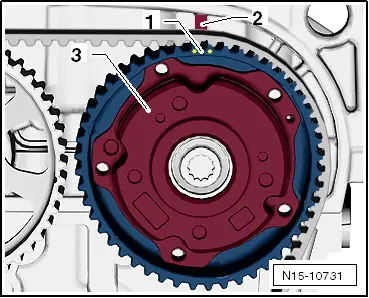
Marked gap -1- of camshaft adjuster -3- is aligned with lug -2- of camshaft housing.
  N15-10731
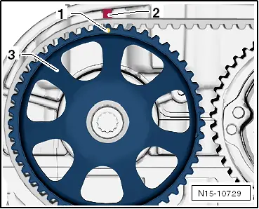
Marked tooth -1- of exhaust camshaft sprocket -3- is aligned with lug -2- of camshaft housing.
  N15-10729
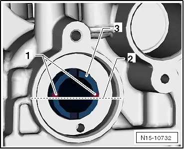
–  Grooves -1- of inlet camshaft -3- are positioned right above horizontal camshaft centre line -2-.
–  Grooves -1- of exhaust camshaft are positioned right above horizontal camshaft centre line -2-.
  N15-10732
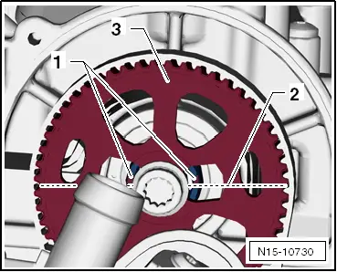
–  Recesses of gear -3- in area of grooves are slightly more oriented above horizontal camshaft centre line.
  Caution
The camshaft clamp -T10477- must slide into position easily.
The camshaft clamp must not be positioned using any kind of hammer.
  N15-10730
–  Insert camshaft clamp -T10477- to stop into camshafts and tighten bolt -arrow- by hand.
If camshaft clamp cannot be fitted:
–  Adjusting valve timing → Chapter.
If camshaft clamp can be fitted:
–  Valve timing is OK.
  Caution
After completing work, it is essential to ensure that the locking pin -T10340- and the camshaft clamp -T10477- have been removed.
Tightening torque of the cylinder block oil filler neck: 30 Nm
Further assembly is basically the reverse of the dismantling sequence.
  N15-10733

Distribution timing: adjustment > < Removing and installing toothed belt