seat Workshop Repair Guides

SEAT Workshop Service and Repair Manuals

Engine lubrication > < Checking distribution timing
Distribution timing: adjustment
   
Distribution timing: adjustment
Special tools and workshop equipment required
t  Support bracket -10 - 222 A-
t  Engine support bracket, basic set -T40091-
t  Assembly tool -T10476-
t  Locating bolt -T10340-
t  Camshaft clamp -T10477-
t  Torque wrench -V.A.G 1332-
t  Adapter -10-222 A/31-2- (not illustrated)
t  Support -10-222 A/31-3- (not illustrated)
t  Adapter -10-222 A/31-5- (not illustrated)
t  Square tube -T40091/1- (not illustrated)
t  Connector -T40091/3- (not illustrated)

Operation process
–  Remove air cleaner housing → Chapter.
   
–  Unlock and disconnect fuel supply line -1- and breather line -2-. → Fuel supply system - Petrol engines; Rep. gr.20.
–  Open line guide -3- and detach hoses.
–  Seal lines so that fuel system is not contaminated by dirt.
–  Detach clamps -arrows-.
  N15-10723
–  Unscrew securing bolt -1- and remove cover -2-.
–  Undo and remove bolts -arrows-.
  N15-10724
–  Unclip duct from the guard.
–  Remove cover -1- and cover -2-.
  N15-10725
–  Unscrew plug -arrow- from crankcase.
–  Lower lifting platform completely.
  Note
t  The lifting platform must be lowered completely in order to allow for screwing the locking pin -T10340- into the crankcase.
t  When the vehicle is raised, the hole is hidden behind the drive shaft.
  N15-10726
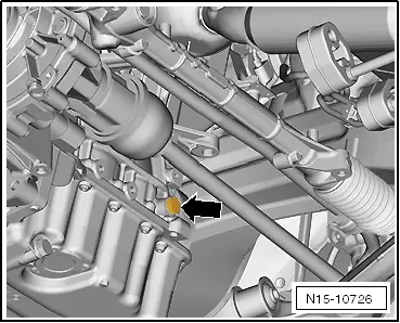
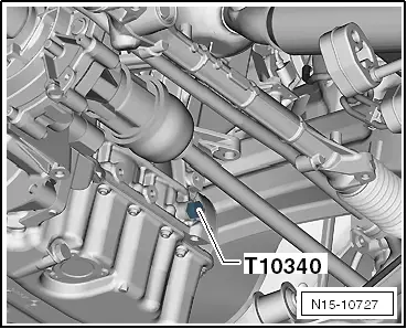
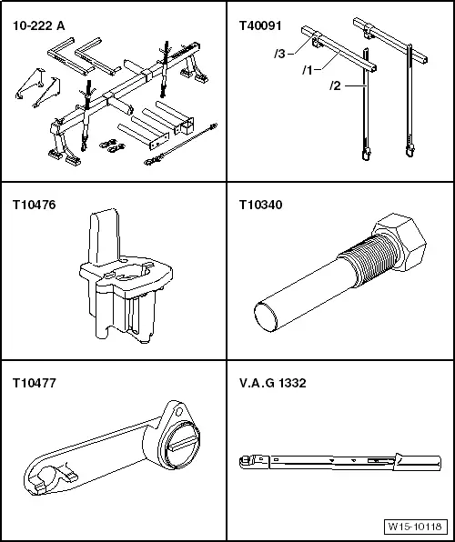
–  Screw locking pin -T10340- into crankcase from above as far as it will go.
  Caution
If locking pin -T10340- cannot be screwed in as far as stop, this indicates that crankshaft is not in the correct position!
In this case, proceed as follows.
–  Unscrew locking pin.
–  Turn crankshaft 90° in direction of rotation of engine.
–  Screw locking pin -T10340- into crankcase as far as it will go.
–  Tighten locking pin -T10340- to 30 Nm.
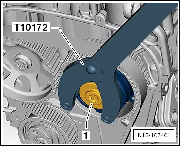
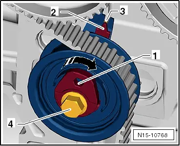
–  Turn crankshaft in direction of rotation of engine as far as the stop.
Locking pin -T10340- locks crankshaft in direction of engine rotation.
–  Removing poly V-belt → Chapter
–  Remove windscreen wiper arms → Electrical system; Rep. gr.92.
–  Remove plenum chamber cover → General body repairs, exterior; Rep. gr.50.
  N15-10727
–  Fit adapter -10-222A/31-2- onto suspension struts.
–  Angle pieces of adapters -arrow- point towards engine compartment.
  N34-11815
–  Position support -10-222A/31-5- above bonnet catch.
–  Correct position is between 2 lugs -arrow-.
  N34-11816
–  Fit support bracket -10 - 222 A- and engine support basic set -T40091- with adapters as shown.
–  Support engine on right eye and slightly release load from assembly mounting by turning spindle.
–  Disconnect earth wire -1-.
  N15-10737
Unscrew securing bolts -arrows- and remove assembly mounting on engine side.
  N10-10670
–  Unscrew securing bolts -1- and swivel alternator in -direction of arrow-.
–  Lift motor up sufficiently by turning spindle in order to allow for unscrewing securing bolt of engine mounting.
  N15-10738
–  Unscrew securing bolts -2- of engine mounting and 3 bolts -1- of lower toothed belt guard.
–  Lift out engine mounting upwards.
  Caution
When loosening and tightening the securing bolts, the camshaft sprockets must in any case be secured with the counterhold -T10172-.
The camshaft clamp -T10477- may not be subjected to load when tightening the camshaft sprockets in order to avoid damage to the tool or to the camshafts.
  N15-10739
–  Secure camshaft adjuster with counterhold -T10172- and unscrew plug -1-.
  Note
When adjusting the valve timing, both camshaft sprockets must be loose.
–  Secure camshaft adjuster and camshaft sprocket with counterhold -T10172-.
  N15-10740
–  Loosen securing bolts -1- and -2-.
–  Loosen securing bolt -3- of belt tensioner and release tension of belt tensioner by turning the eccentric -4- (hexagon socket insert) in -direction of arrow-.
–  Push toothed belt from camshaft sprockets.
  N15-10741
–  Renew securing bolts -1- and -2- and tighten them hand-tight.
–  Rotate camshafts via securing bolts -1- and -2- into positions described below.
  N15-10762
–  Grooves -1- of inlet camshaft -3- are positioned right above horizontal camshaft centre line -2-.
–  Grooves -1- of exhaust camshaft are positioned right above horizontal camshaft centre line -2-.
  N15-10732
–  Recesses of gear -3- in area of grooves are slightly more oriented above horizontal camshaft centre line.
  Caution
The camshaft clamp -T10477- must slide into position easily.
The camshaft clamp must not be positioned using any kind of hammer.
  N15-10730
–  Insert camshaft clamp -T10477- to stop into camshafts and tighten bolt -arrow- by hand.
–  Loosen securing bolts of camshaft sprockets until sprockets can easily be rotated by hand.
  N15-10733
Align marked gap -1- of camshaft adjuster -3- with lug -2- of camshaft housing.
  N15-10731
Align marked tooth -1- of exhaust camshaft sprocket -3- with lug -2- of camshaft housing.
  N15-10729
–  Markings -1- and -2- on camshaft sprockets are aligned as shown.
Groove -3- for assembly tool -T10476- is located on exhaust camshaft sprocket.
–  Insert assembly tool -T10476- between camshaft sprockets.
  N15-10763
–  Arrows -1- on assembly tool are aligned with marks -2- on camshaft sprockets.
  Note
When the assembly tool -T10476- is inserted, the marks -2- on the camshaft sprockets are slightly offset.
  N15-10764
–  Dowel pin -1- of assembly tool -T10476- must engage in groove -2- of exhaust camshaft sprocket.
–  Hand-tighten belt tensioner -3- on cylinder head.
  N15-10765
–  Hook -1- must be positioned in recess -2-.
–  Orientation of eccentric -4- of belt tensioner must be as shown.
  Note
t  In this position the belt tensioner is completely free of tension.
t  When installing the toothed belt, ensure that the assembly tool -T10476- is correctly positioned between the camshaft sprockets.
–  Toothed belt must make full contact with crankshaft sprocket.
–  Check if the crankshaft is in cylinder 1 TDC position.
The crankshaft must make contact with the locking pin -T10340- in direction of engine rotation.
  N15-10766
–  Fit toothed belt -1- onto belt tensioner -5- and camshaft sprocket -2-.
–  Then fit toothed belt on camshaft adjuster -3- and on idler roller -4-.
–  Remove assembly tool -T10476- from camshaft sprockets.
–  First turn the eccentric -1- in the -direction of the arrow- until the adjustment pointer -2- is positioned about 10 mm to the right of the setting window -3-.
  N15-10798
–  Then rotate eccentric of belt tensioner back using hexagon socket insert at position -1- until adjustment pointer -2- is exactly centred in adjustment window -3-.
–  Hold eccentric in that position using hexagon socket insert at position -1-.
–  Tighten securing bolt -4- to 25 Nm.
  Note
t  When the engine has been rotated by hand or by engine operation, the position of the adjustment pointer -2- might be slightly offset from the adjustment window -3-.
t  However, this has no relevant influence on the valve timing.
–  Secure camshaft adjuster and exhaust camshaft sprocket with counterhold -T10172-.
  N15-10768
–  Tighten securing bolts -1- and -2- to 50 Nm.
  Note
The securing bolts will be tightened with a further tightening angle of 90° at the end of the work sequence after the valve timing has been checked.
  N15-10771
–  Remove locking pin -T10340- from above with lifting platform lowered.
  N15-10727
–  Unscrew bolt -arrow- and remove camshaft clamp -T10477-.
–  Turn crankshaft 2 turns in direction of rotation of engine.
–  Screw locking pin -T10340- into crankcase as far as it will go.
  Caution
The camshaft clamp -T10477- must slide into position easily.
The camshaft clamp must not be positioned using any kind of hammer.
–  Insert camshaft clamp -T10477- to stop into camshafts and tighten bolt by hand.
The valve timing is OK, if the camshaft clamp -T10477- can be pushed into the camshafts.
If control times are not OK
–  Repeat adjustment of valve timing.
–  Remove camshaft clamp -T10477-.
–  Secure camshaft adjuster and exhaust camshaft sprocket with counterhold -T10172-.
  N15-10733
–  Turn securing bolts -1- and -2- 90° further.
–  Renew O-ring of plug if damaged.
  N15-10771
–  Tighten camshaft adjuster plug -1- to 20 Nm.
  N15-10772
–  Remove locking pin -T10340- from above with lifting platform lowered.
  Caution
After completing work, it is essential to ensure that the locking pin -T10340- and the camshaft clamp -T10477- have been removed.
Tightening torques
Tightening torque of the cylinder block oil filler neck: 30 Nm
Assembly overview - cylinder block (pulley end) → Chapter.
Assembly overview - assembly mountings → Chapter
Further assembly is basically the reverse of the dismantling sequence.
  N15-10727

Engine lubrication > < Checking distribution timing