
Leon Mk1
| Dismantling and assembling pistons and conrods |

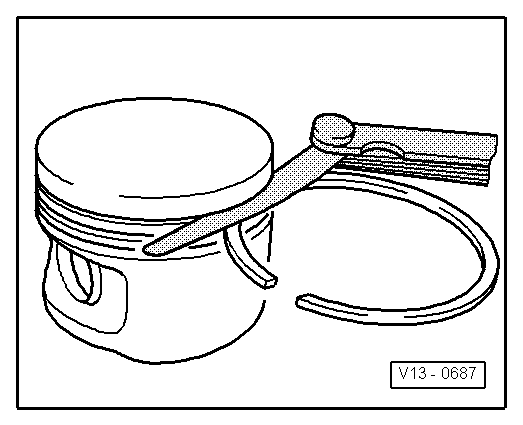
| 1 - | Piston ring |
| q | Offset gaps by 120 ° |
| q | Remove and install with piston ring pliers |
| q | “TOP” faces towards piston crown |
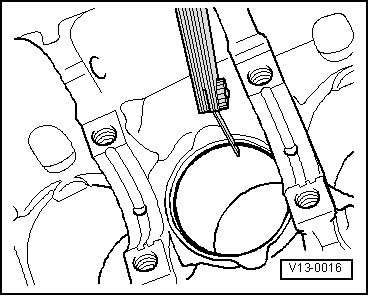
| q | Checking ring gap → Fig. |
| q | Checking ring to groove clearance → Fig. |
| 2 - | Piston |
| q | With combustion chamber |
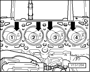
| q | Mark installation position and cylinder number |
| q | Mark installation position and allocation piston/cylinder → Fig. |
| q | Arrow on piston crown points to pulley end |
| q | Install using piston ring clamp |
| q | Cracks on piston skirt, renew piston |
| q | Checking piston projection at TDC → Chapter |
| 3 - | Piston pin |
| q | If difficult to remove, heat piston to 60 °C |
| q | Remove and install with punch -U-20008- |
| 4 - | Circlip |
| 5 - | Conrod |
| q | Only renew as a set |
| q | Mark cylinder number -A- |
| q | Installation position: Marking -B- faces towards pulley end |
| 6 - | Bearing shell |
| q | Note installation position |
| q | Do not interchange used bearing shells |
| q | Ensure retaining lugs fit tightly in recesses |
| q | Axial clearance Wear limit: 0.37 mm |
| q | Check radial clearance with Plastigage: Wear limit: 0.08 mm Do not rotate crankshaft when checking radial clearance |
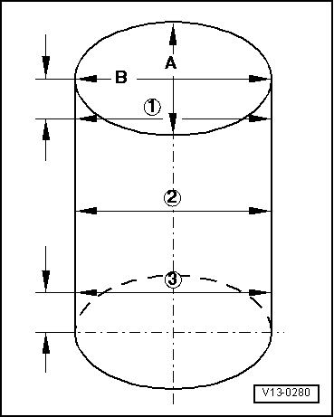
| 7 - | Cylinder block |
| q | Checking cylinder bores → Fig. |
| q | Piston and cylinder dimensions → Chapter |
| 8 - | Conrod bearing cap |
| q | Note installation position |
| 9 - | Oil spray jet |
| q | For piston cooling |
| 10 - | 25 Nm |
| q | Insert without sealant |
| 11 - | Conrod bolt, 30 Nm + 1/4 turn (90 °) further |
| q | Renewing |
| q | Oil threads and contact surface |
| q | The quarter turn further can be done in several stages. |
| q | The turning further angle can be measured with protractor -T20030- |
| q | To measure radial clearance use old bolts |
|
|
| Piston ring Dimensions in mm | New | Wear limit |
| 1st compression ring | 0.20...0.40 | 1.0 |
| 2nd compression ring | 0.20...0.40 | 1.0 |
| Oil scraper ring | 0.25...0.50 | 1.0 |
|
|
| Piston ring Dimensions in mm | New | Wear limit |
| 1st compression ring | 0.06...0.09 | 0.25 |
| 2nd compression ring | 0.05...0.08 | 0.25 |
| Oil scraper ring | 0.03...0.06 | 0.15 |
 Note!
Note!
|
|