seat Workshop Repair Guides

SEAT Workshop Service and Repair Manuals

Ignition system, glow plug system > < Exhaust gas recirculation system
Checking process
Checking process
The working of the exhaust gas recirculation is checked with function 04 (basic adjustment). In this way, every 10 seconds the exhaust gas recirculation valve is timed.
–  Connect the -V.A.G 1551 (V.A.G 1552)- unit and, using the corresponding “address code” 01, select the control unit for engine electronics. When you do this, the engine should be idling: → Rep. Gr.01
   
Indication on the display:
–  Press the keys 0 and 4 for the function “Begin basic adjustment” and confirm with Q.
 
Fast data transmission              HELP
Select the function XX                  
Indication on the display:
–  Press the keys 0, 0 and 3 for “Indication group number 3” and confirm with Q.
 
Basic adjustment                    HELP
Enter indication group number XXX       
Indication on the display: (1…4 = indication fields)
The indication in field 2 should actively oscilate every 10 s between EGR activ. and EGR inact.
The value that appears in indication field 4 must oscilate within the following regulation margin:
EGR inact.
–  Theoretical value indication field
   0…5 %
EGR activ.
–  Theoretical value indication field 4
   94…96 %
If the theoretical values are not reached:
–  Check the exhaust gas recirculation mechanical valve → Chapter.
–  Check the flexible depression pipes → Chapter.
–  Check the exhaust gas recirculation valve -N18- as follows:
–  Press .
–  Press the keys 0 and 6 for the function “End data transmission” and confirm with Q.
–  Turn off the ignition.
 
Basic adjustment system 3             ->
900/mind.       EGR inact            0 %
–  Extract the connector -1- from the exhaust gas recirculation valve -2-.
–  Measure the resistance in the valve.
   Theoretical value: 14...20 Ω
If the theoretical value is not reached:
–  Replace the exhaust gas recirculation valve -N18-.
  Note!
At room temperature, the resistance lies in the lower tolerance field; with the engine at service temperature, in the upper tolerance field.
If the theoretical value is reached:
–  Turn on the ignition.
  N26-0358
–  Measure the supply voltage of the valve on contact -1- of the connector and engine ground.
   Theoretical value: approx. voltage of the battery.
If the theoretical value is not reached:
–  Turn off the ignition.
  V96-0749
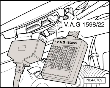
–  Connect the -V.A.G 1598/22- checking box to the cable harness of the control unit.
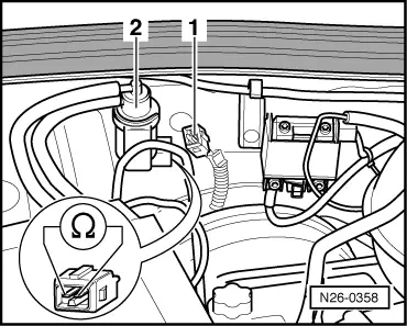
–  Check for breakage in the cables between the checking box and the connector, following the current circuit diagrams.
   Contact 1+female 2+28
   Contact 2+female 29
   Cable resistance: 1,5 Ω max.
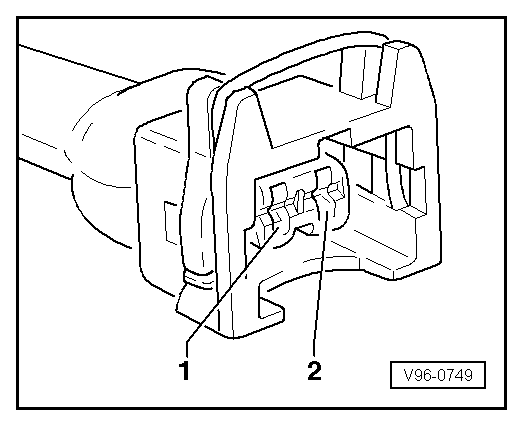
–  Additionally, check the cables for short circuiting between them, to ground and to battery positive.
   Theoretical value: ∞ Ω
If no fault is found in the cables:
–  Replace the control unit of the diesel direct injection system -J248-: → Rep. Gr.23
  N24-0709

Ignition system, glow plug system > < Exhaust gas recirculation system