
Leon Mk1
| Piston and conrod removing and installing |
 Note
Note| Before carrying out any assembly work, it is necessary to lubricate points of support and sliding surfaces |

| 1 - | Piston |
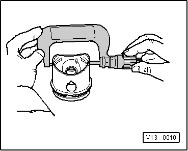
| q | Checking → Fig. |
| q | Mark installation position and piston/cylinder correspondence |
| q | Arrow on piston crown points to crankshaft pulley end |
| q | Install using piston ring sleeve |
| q | Piston and cylinder dimensions → Chapter |
| 2 - | Piston pin |
| q | If difficult to move, heat piston to 60°C |
| q | Remove and install with tool -T20019- |
| 3 - | Safety washer |
| q | Renew |
| 4 - | Conrod |
| q | Only renew as a set |
| q | Mark cylinder number -A- |
| q | Markings -B- should face towards pulley end |
| q | Guided axially via piston |
| 5 - | Bearing shell |
| q | Do not interchange used bearing shells |
| q | Place bearing shells in correct position |
| q | Check radial clearance with Plastigage |
| q | New: 0,020 … 0,061 mm |
| q | Wear limit: 0.091mm |
| q | Do not rotate the crankshaft when checking the radial clearance |
| 6 - | Cylinder block |
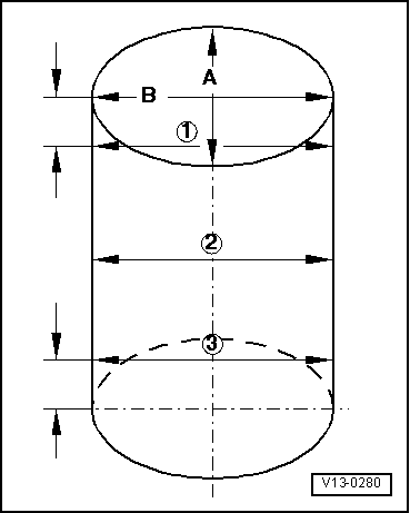
| q | Cylinder bores: checking → Fig. |
| q | Piston and cylinder dimensions → Chapter |
| 7 - | Conrod bearing caps |
| q | Note the fitting position |
| q | The caps only fit in one position and only on the appropriate conrod, this is due to the breaking procedure (cracking) separating the cap from the conrod |
| 8 - | 30 Nm + 1/4 turn (90°) |
| q | Renew |
| q | Oil the threads and contact surface |
| q | To measure radial clearance tighten to 30 Nm but not further |
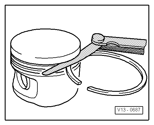
| 9 - | Oil scraper rings |
| q | Carefully remove and install 3-part oil scraper rings by hand |
| q | “TOP” faces towards piston crown |
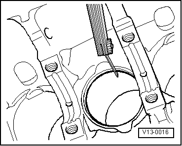
| q | Ring gap: checking → Fig. |
| q | Ring to groove clearance: checking → Fig. |
| 10 - | Compression rings |
| q | Offset gaps by 120 ° |
| q | Remove and install with piston ring pliers |
| q | “TOP” faces towards piston crown |
| q | Ring gap: checking → Fig. |
| q | Ring to groove clearance: checking → Fig. |
| Piston ring | Wear limit |
| 1. Compression ring | 1.0 mm |
| 2. Compression ring | 1.0 mm |
| Oil scraper ring | 1.0 mm |
|
|
| Piston ring | Wear limit |
| 1. Compression ring | 0.25 mm |
| 2. Compression ring | 0.15 mm |
| Oil scraper ring | 0.15 mm |
|
|
Note
|
|