
Leon Mk1
| Ignition transformer -N152- checking |
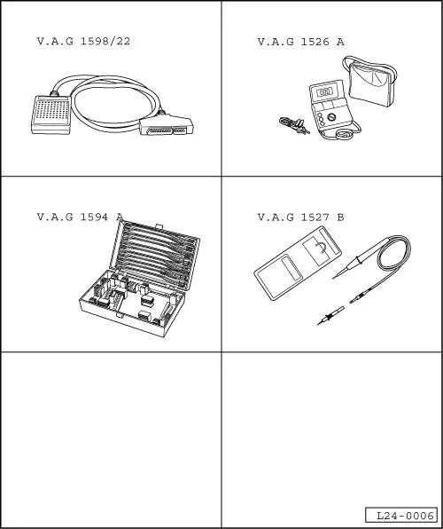
| Special tools and workshop equipment required |
| t | Hand multimeter -V.A.G 1526 A- or multimeter -V.A.G 1715- |
| t | Diode test lamp -V.A.G 1527 B- |
| t | auxiliary measuring set -V.A.G 1594 A- or -V.A.G 1594 C- |
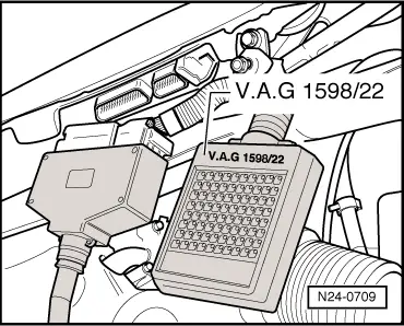
| t | Test box -V.A.G 1598/22- |
| t | Current flow diagram |
|
|
|
|
|
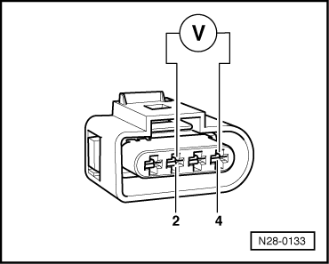
| Connector, contact | Connector, contact |
| 2 | 4 |
| Switch ignition on | |
| Specification: 11.5 V min. | |
|
|
|
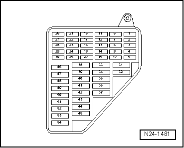
| Connector, contact | Relay plate |
| 2 | fuse 42 |
| 4 | earth |
| Specification: 1.5 Ω max. | |
|
 WARNING
 Note
Note
|
|
|
|
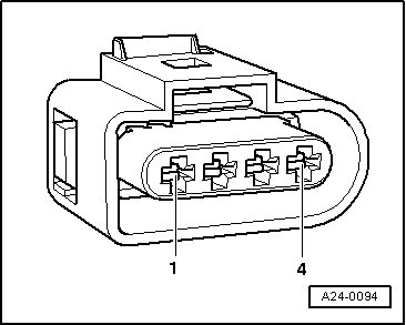
| Connector, contact | Connector, contact |
| 1 (ignition output 1) | 4 |
| 3 (ignition output 2) | 4 |
|
|
|
|
|
| Connector, contact | Test box -V.A.G 1598/22-, socket |
| 1 | 57 |
| 3 | 71 |
| Specification: 1.5 Ω max. | |
|
|
|
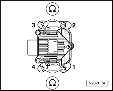
| Cyl. (see illustration) | Cyl. (see illustration) |
| 1 | 4 |
| 2 | 3 |
| Specification: 4.0 … 6.0 kΩ (at 20 °C) | |
|