seat Workshop Repair Guides

SEAT Workshop Service and Repair Manuals

Servicing valve gear > < Kolben- und Zylinderma?e
Dismount
Dismount
  Note!
t  Where engine repairs do not require the cylinder head to be dismantled, the cylinder head can be removed without removing the cylinder head cover or the camshaft.
t  Then start at work sequence 1.
If the cylinder head is to be dismantled → .
Work sequence 1
–  First check whether a coded radio is fitted. If this is the case obtain the anti-theft coding.
–  With the ignition switched off disconnect battery earth strap.
–  Remove air cleaner → Chapter, Dismantling and assembling air cleaner.
–  Remove ribbed belt → Chapter.
–  Release toothed belt tensioning roller and take toothed belt off camshaft sprocket. For work sequence → Chapter, Removing, installing and tensioning toothed belt.
–  Remove camshaft sprocket. Hold camshaft sprocket with counter-hold -T20018A- when loosening the bolt.
–  Remove the 3 upper bolts from the rear of the toothed belt guard.
–  Open the cylinder head cover sealing cap, then unclip the screening cover and take out.
   
–  Pull 4-pin connector off ignition transformer -arrow-.
  E28-0002
–  Pull 3-pin connector off Hall sender -arrow-.
Work sequence 2
–  Remove cylinder head cover and camshaft → Chapter.
Continuation for work sequences 1 and 2
–  Remove screw which secures the oil dipstick guide tube.
–  Remove lifting eye in area of oil filler opening.
  E28-0003
–  Remove the fuel supply pipe -1- and the return pipe -2- together with the suspension tower (press release button).
  Caution
Fuel supply pipes are under pressure! Before removing from hose connection wrap a cloth around the connection. Then release pressure by carefully pulling hose off connection.
–  Seal the pipes so that the fuel system is not contaminated by dirt etc.
–  Open the cap of the coolant reserve tank in order to release the pressure from the cooling system.
–  Drain coolant → Chapter.
–  Loosen hose clips and pull coolant hoses off coolant thermostat housing.
–  Loosen or separate the following components:
t  The hose from intake manifold to activated charcoal canister system.
t  The vacuum hose from inlet manifold to brake servo.
t  The 2-pin connector from knock sensor (rear of cylinder block).
t  The Lambda probe connector (on front assembly mounting) and pull the connecter out from the bracket.
t  The 6-pin connector for the throttle valve control part.
t  The 4-pin connector for the intake manifold pressure sender with intake air temperature sender on right of intake manifold.
t  The connector for the engine regime transmitter.
t  The connector from coolant temperature sender and oil pressure switch.
t  The main collective connector below the coolant thermostat housing.
  E10-0018
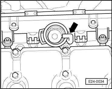
–  Pull the vacuum hose off fuel pressure regulator -arrow-.
–  Remove the fuel rail complete with injectors from cylinder head → Chapter, Dismantling and assembling fuel rail with injectors.
–  Separate front exhaust pipe from exhaust manifold → Chapter, exhaust manifold, front exhaust pipe and catalyst with attachments.
Removing cylinder head
–  Extraer de la carcasa del termostato la grapa de fijación del tubo de líquido refrigerante que va a la bomba de líquido refrigerante.
–  Extract the coolant thermostat casing from its housing in the cylinder head .
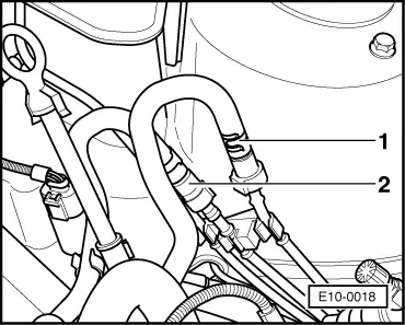
–  Remove the flexible pipes for coupling together, those for the coolant, those for negative pressure and those for induction from the cylinder head.
  E24-0034
–  Loosen the bolts from the cylinder head in the order stated and remove them using the M12 wrench from the set of cogged wrenches -U-40020-.
–  Carefully lift cylinder head off.
  N15-0026

Servicing valve gear > < Kolben- und Zylinderma?e