
Leon Mk1
| Piston and connecting rod: disassembly and assembly |

| 1 - | Piston rings |
| q | Stagger the cuts by 120° |
| q | Remove and install, with the help of pliers for rings |
| q | Carefully remove and install the oil scraper rings made up of three pieces, by hand |
| q | The word “TOP” indicates the piston head |
| q | Check the play at the ends of the rings → Fig. |
| q | Check the play between piston rings and piston grooves → Fig. |
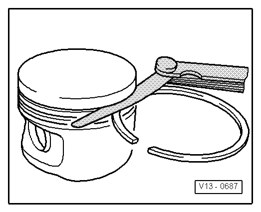
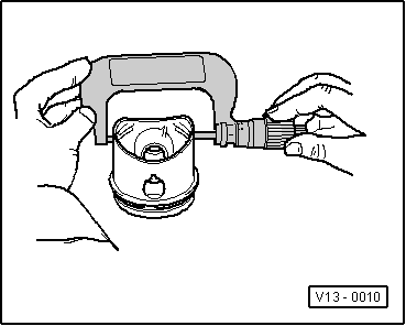
| 2 - | Piston |
| q | Check → Fig. |
| q | Mark the assembly position and the cylinder to which it belongs. |
| q | The arrow on the piston head should point toward the pulley. |
| q | Assemble with casing to assemble rings. |
| 3 - | Piston pin |
| q | If difficult to move, heat the piston to 60° |
| q | Remove and install with -T20019- |
| 4 - | Securing washer |
| 5 - | Connecting rod |
| q | Renew unit only |
| q | Mark the position on cylinder -A- |
| q | Assembly position: the marks -B- should point toward the pulley |
| q | Axial guided by piston |
| 6 - | Half bearings |
| q | Place the half bearings on the block, ensuring they are centred |
| q | Ensure that used half bearings are not used. |
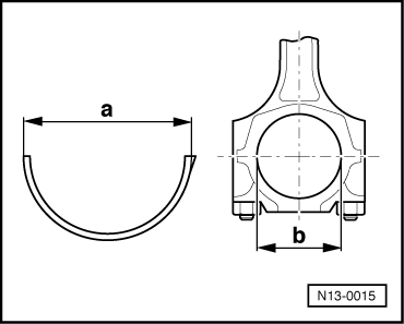
| First measure pre-tension → Fig. |
| q | Measure the radial play with Plastigage: |
| New: 0.020 … 0.061 mm |
| Wear limit: 0.091 mm |
| When measuring the radial play do not turn the crankshaft. |
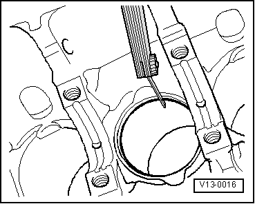
| 7 - | Engine block |
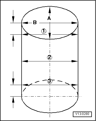
| q | Check the bore of the cylinders → Fig. |
| q | Pistons and cylinder dimensions → Chapter |
| 8 - | Connecting rod caps |
| q | Check the assembly position |
| q | If the connecting rods are cracked, the cap can only be placed in one position, and only on a given connecting rod |
| 9 - | Connecting rod bolt |
| M7: 20 Nm + 1/4 turn (90°) |
| M8: 30 Nm + 1/4 turn (90°) |
| q | Renew |
| q | Apply lubricant to the threads and contact surface |
| q | To measure the radial play, tighten to 20 or 30 Nm, without retightening. |
| Piston ring | Wear limit | |
| Ring compression | 1.0 mm | |
| Oil scraper rings | 1 piece 3 pieces | 1.0 mm _ → Note |
| 1) | It is not possible to make an indication as to the wear limit. |
|
|
| Piston ring | Wear limit | |
| Ring compression | 0.15 mm | |
| Oil scraper rings | 1 piece 3 pieces | 0.15 mm not measured |
|
|
 Note!
Note!
|
|
|
|
| dimension -a- of the half bearing | |
| - | diameter of the connecting rod -b- |
| = | pre-tension |
|