
Leon Mk1
| Assembly diagram |
 Note!
Note!| t | To carry out assembly work, the engine must be attached to engine support -Ar-2204 A- together with flanges -T20082-. |
| t | Before removing the crankshaft, prepare an appropriate base so that the generator wheel ( → Item) is not supported or damaged. |

| 1 - | Oil pump |
| q | Removing and installing → Chapter |
| 2 - | 15 Nm |
| 3 - | Chain sprocket |
| q | For oil pump drive |
| 4 - | Half bearings 1, 2, 3, 4 and 5 |
| q | Classification for parts ordering → Fig. |
| q | For cap without lubrication slot |
| q | For engine block with lubrication slot |
| q | Do not swap used half bearings (mark them) |
| 5 - | 40 Nm + 90° (1/4 turn) |
| q | Replace |
| q | Continuous thread |
| q | Tighten to 40 Nm for measurement of crankshaft radial play |
| 6 - | Caps |
| q | Cap 1: Pulley side |
| q | Cap 3 with slots for drive washers |
| q | The tabs of the engine block half bearings and of the caps must coincide |
| 7 - | Bearing shell 3 |
| q | → Item |
| 8 - | Sender wheel |
| q | Renew |
| q | For engine speed sender -G28- |
| q | Can only be installed in one position. Holes are off-set |
| 9 - | 10 Nm + 1/4 turn (90°) further |
| q | Renew |
| 10 - | Thrust washer |
| q | For bearing 3 bearing cap |
| q | The lubrication slots face outwards |
| q | Check the fastening |
| 11 - | Crankshaft |
| q | Axial clearance new: 0,07 … 0,23 mm |
| Wear limit: 0,30 mm |
| q | Check radial clearance with Plastigage |
| New: 0,01 … 0,04 mm |
| Wear limit: 0,15 mm |
| q | Do not rotate the crankshaft when checking the radial clearance |
| q | Crankshaft dimensions → Chapter |
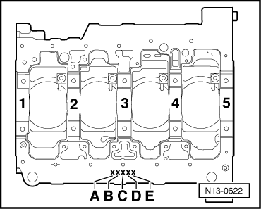
| A = | Mark for bearing 1 |
| B = | Mark for bearing 2 |
| C = | Mark for bearing 3 |
| D = | Mark for bearing 4 |
| E = | Mark for bearing 5 |
|
| S = | Black |
| R = | Red |
| G = | Yellow |
| B = | Blue |
|