
Leon Mk1
| Assembly diagram |
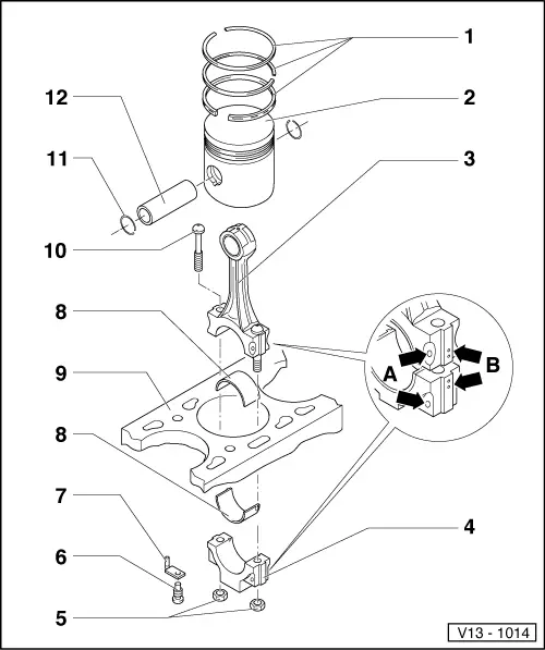
| 1 - | Piston ring |
| q | Offset gaps by 120° |
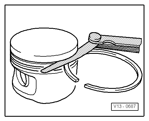
| q | Remove and install with piston ring pliers |
| q | “TOP” faces towards piston crown |
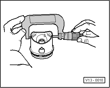
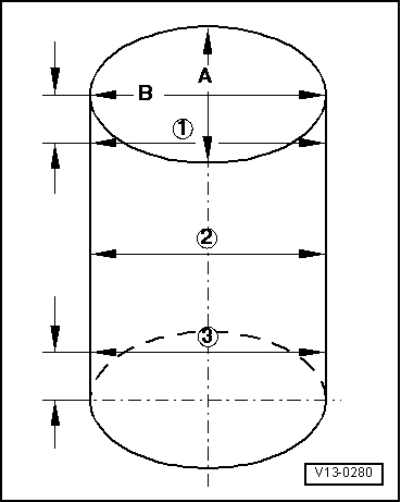
| q | Checking ring gap → Fig. |
| q | Checking ring to groove clearance → Fig. |
| q | 2 or 3 part oil scraper ring, mixed installations permissible |
| 2 - | Piston |
| q | Checking → Fig. |
| q | Mark installation position and cylinder number |
| q | Arrow on piston crown points to pulley end |
| q | Install using piston ring clamp |
| 3 - | Conrod |
| q | Only renew as a set |
| q | Mark cylinder number -B- |
| q | Installation position: Marking -A- faces towards pulley end |
| 4 - | Conrod bearing cap |
| q | Note installation position |
| 5 - | 30 Nm + 1/4 turn (90°) further |
| q | Oil threads and contact surface |
| q | To measure radial clearance tighten to 30 Nm but not further |
| 6 - | Pressure relief valve, 27 Nm |
| q | Opening pressure: 2,5 … 3,2 bar |
| 7 - | Oil spray jet |
| q | For piston cooling |
| 8 - | Bearing shell |
| q | Note installation position |
| q | Do not interchange used bearing shells |
| q | Ensure retaining lugs fit tightly in recesses |
| q | Axial clearance |
| New: 0,05 … 0,31 mm |
| Wear limit: 0,37 mm |
| q | Check radial clearance with Plastigage: |
| New: 0,01 … 0,06 mm |
| Wear limit: 0,12 mm |
| Do not rotate crankshaft when checking radial clearance |
| 9 - | Cylinder block |
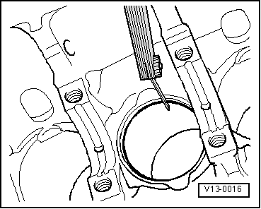
| q | Checking cylinder bores → Fig. |
| q | Piston and cylinder dimensions → Chapter |
| 10 - | Conrod bolt |
| 11 - | Circlip |
| 12 - | Piston pin |
| q | If difficult to remove, heat piston to 60 °C |
| q | Remove and install with -T20019- |
|
|
| Piston ring | Gap | ||
| New | Wear limit | ||
| Compression rings | mm | 0,20…0,40 | 0,8 |
| Oil scraper ring | mm | 0,25…0,50 | 0,8 |
|
|
| Piston ring | Gap | ||
| New | Wear limit | ||
| Compression rings | mm | 0,06…0,09 | 0,20 |
| Oil scraper ring | mm | 0,03…0,06 | 0,15 |
 Note!
Note!
|
|