
Leon Mk1
| Assembly diagram |
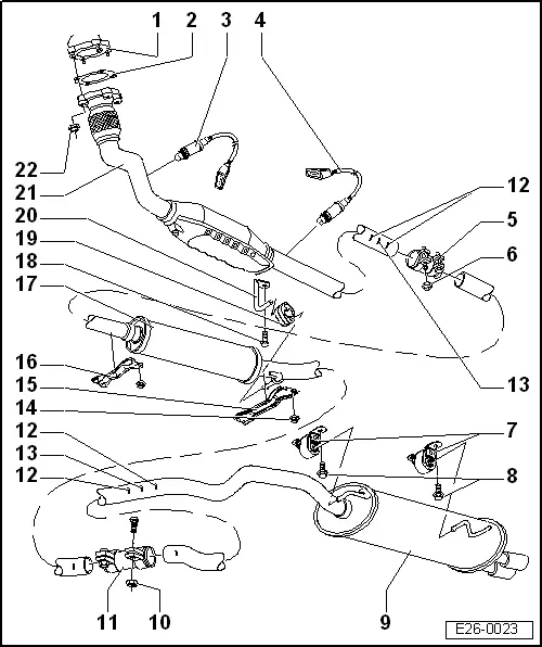
| 1 - | Turbocharger |
| q | Removing and installing → Chapter |
| 2 - | Gasket |
| q | Renew |
| 3 - | Lambda probe 1 in front of catalytic converter -G39-, 50 Nm |
| q | Grease only the threads with -G 052 112 A3-; -G 052 112 A3- must not get into the slots on the probe body |
| q | Remove and install with -U-40080- |
| 4 - | Lambda probe 2 after catalytic converter -G130-, 50 Nm |
| q | Grease only the threads with -G 052 112 A3-; -G 052 112 A3- must not get into the slots on the probe body |
| q | Remove and install with -U-40080- |
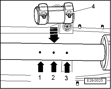
| 5 - | Double clamp |
| q | Note installation position → Fig. |
| 6 - | 40 Nm |
| q | Renew |
| 7 - | Mounting |
| 8 - | 20 Nm + 1/4 turn (90°) further |
| 9 - | Rear silencer |
| 10 - | 40 Nm |
| 11 - | Double clamp |
| 12 - | Marking |
| q | Visible from below |
| q | For centering double clamp |
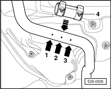
| 13 - | Separating point |
| q | If, in cases of repair, the exhaust pipe is supplied in one piece, cut-through exhaust pipe at separating point as marked. |
| q | Note installation position → Fig. |
| q | Align middle and rear silencer free of stress |
| 14 - | 20 Nm |
| 15 - | Tunnel bridge |
| 16 - | Protective plate |
| 17 - | Centre and rear silencer |
| 18 - | 25 Nm |
| 19 - | Mounting |
| q | Note installation position |
| 20 - | Mounting |
| 21 - | Front exhaust pipe with catalytic converter |
| 22 - | 40 Nm |
|
|