
Leon Mk1
| Dismantling and assembling pistons and conrods |

| 1 - | Circlip |
| 2 - | Piston pin |
| q | If difficult to remove, heat piston to 60°C |
| q | Remove and install with drift -T20019- |
| 3 - | Piston |
| q | Checking → Fig. |
| q | Mark installation position and cylinder number |
| q | Arrow on piston crown points to pulley end |
| q | Install using piston ring clamp |
| 4 - | Compression rings |
| q | Offset gaps by 120° |
| q | Remove and install compression rings with piston ring pliers |
| q | “TOP” faces towards piston crown |
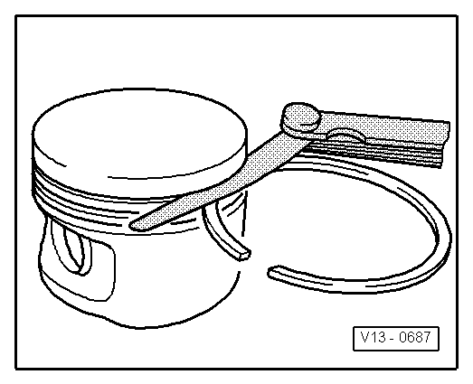
| q | Checking ring gap → Fig. |
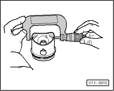
| q | Checking ring to groove clearance → Fig. |
| 5 - | Oil scraper ring |
| q | Remove and install 2-part oil scraper rings carefully by hand |
| q | “TOP” faces towards piston crown |
| q | Checking ring gap → Fig. |
| q | Checking ring to groove clearance → Fig. |
| 6 - | Conrod |
| q | Only renew as a set |
| q | Mark cylinder number -A- |
| q | Installation position: Marking -B- faces towards pulley end |
| q | Guided axially via piston |
| 7 - | Conrod bearing cap |
| q | Note installation position |
| q | Link rods split through cracking may only be placed in one position and only with the proper link rod |
| 8 - | Conrod bolt, 20 Nm + 1/4 turn (90°) further |
| q | Renewing |
| q | Oil threads and contact surface |
| q | To measure radial clearance tighten to 20 Nm but not further |
| q | The turning further can be done in several stages |
| q | The turning further angle can be measured with protractor -T20030- |
| 9 - | Aluminium cylinder block |
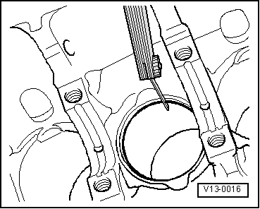
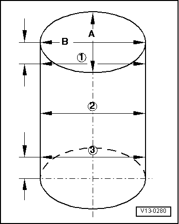
| q | Checking cylinder bores → Fig. |
| q | Piston and cylinder dimensions → Chapter |
| 10 - | Bearing shell |
| q | Do not interchange used bearing shells |
| q | Insert bearing shells in the centre |
| q | Check radial clearance with Plastigage: New: 0.020...0.061 mm Wear limit: 0.091 mm Do not rotate crankshaft when checking radial clearance |
|
|
| Piston segment | Wear limit | |
| for compression | 1.0 mm | |
| oil scraper | 1.0 mm | |
|
|
| Piston segment | Wear limit | |
| Kompressionsring | 0.15 | |
| Ölabstreifring | 0.15 | |
|
|
 Note!
Note!
|
|