seat Workshop Repair Guides

SEAT Workshop Service and Repair Manuals

Checking signal from brake light switch and brake pedal switch > < Checking speed signal
Checking signal from/to air conditioning system
Special tools and workshop equipment required
t  Fault reader -V.A.G 1551- or vehicle system tester -V.A.G 1552- with cable -V.A.G 1551/3A-
t  
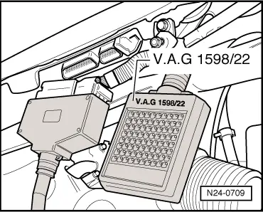
Test box -V.A.G 1598/22-
t  Hand multimeter -V.A.G 1526- or multimeter -V.A.G 1715-
t  Adapter set -V.A.G 1594-
t  Current flow diagram
Test conditions
l  All electrical consumers, e.g. lights and rear window heating must be switched off.
l  Air conditioner functioning OK.
l  Air conditioner must be switched off
l  Vehicle at room temperature (warmer than + 15 °C).
l  No faults must be stored in fault memory → Vehicle diagnosis, testing and information system VAS 5051, interrogating and erasing fault memory.
Test sequence
–  Connect fault reader -V.A.G 1551- (-V.A.G 1552-). Start engine and select “Address word” 01 of engine control unit. When doing this the engine must be running at idling speed. (Connecting fault reader and selecting engine control unit → Vehicle diagnosis, testing and information system VAS 5051.)
   
Indicated on display:
–  Press keys 0 and 8 for the function “Read measured value block” and confirm entry with Q key.
 
Rapid data transfer                 HELP
Select function XX                      
Indicated on display:
–  Press keys 0, 5 and 0 for “Display group number 50” and confirm entry with Q key.
 
Read measured value block               
Input display group number XXX          
Indicated on display: (1...4 = Display zones)
–  Observe display in display zone 3. It must show A/C-Low.
–  Observe display in display zone 4. It must show Compr. OFF.
–  Switch on air conditioning system.
–  Select lowest temperature and highest blower speed.
The display in display zone 3 must change to A/C-High.
The display in display zone 4 must change to Compr. ON.
–  Floor accelerator pedal quickly and then release (brief burst of throttle).
The display in display zone 4 must change from Compr.ON to Compr. OFF for a few seconds (compressor switch-off when vehicle is accelerating).
–  Press the key.
–  Press keys 0 and 6 for the “End output” function and confirm input with the Q key.
–  Switch off ignition.
If the display does not change:
–  Remove wiper arms and cowl panel: → Electrical system; Rep. Gr.92
 
Read measured value block 50           →
–  Connect test box -V.A.G 1598/22- to control unit wiring harness.
–  Check wiring for open circuit between test box sockets 17 + 42 and air conditioner using current flow diagram. Wire resistance: max. 1.5 Ω
If no fault can be found in the wiring:
–  Interrogate fault memory, if necessary, repair any faults and then erase fault memory → Vehicle diagnosis, testing and information system VAS 5051, interrogating and erasing fault memory.
–  Check function of air conditioner control unit.
  N24-0709

Checking signal from brake light switch and brake pedal switch > < Checking speed signal