seat Workshop Repair Guides

SEAT Workshop Service and Repair Manuals

Checking signal from/to air conditioning system > < Checking additional signals
Checking speed signal
Special tools and workshop equipment required
t  Fault reader -V.A.G 1551- or vehicle system tester -V.A.G 1552- with cable -V.A.G 1551/3A-
t  
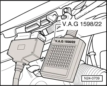
Test box -V.A.G 1598/22-
t  Hand multimeter -V.A.G 1526- or multimeter -V.A.G 1715-
t  Adapter set -V.A.G 1594-
t  Current flow diagram
Check conditions
l  The battery voltage must be at least 11.5 V.
l  Speedometer must be OK., checking speedometer: → Electrical system; Rep. Gr.90
l  No faults must be stored in fault memory → Vehicle diagnosis, testing and information system VAS 5051, interrogating and erasing fault memory.
Test sequence
  Note!
To check the speed signal the vehicle must be driven. To do this a second person is necessary.
  Caution
Secure fault reader to rear seat and operate from this position.
Observe the valid safety precautions when carrying out a road test → Chapter.
–  Connect fault reader -V.A.G 1551- (-V.A.G 1552-). Start engine and select “Address word” 01 of engine control unit. When doing this the engine must be running at idling speed. (Connecting fault reader and selecting engine control unit → Vehicle diagnosis, testing and information system VAS 5051.)
   
Indicated on display:
–  Press keys 0 and 8 for the function “Read measured value block” and confirm entry with Q key.
 
Rapid data transfer                 HELP
Select function XX                      
Indicated on display:
–  Press keys 0, 0 and 5 for “Display group number 5” and confirm entry with Q key.
 
Read measured value block               
Input display group number XXX          
Indicated on display: (1...4 = Display zones)
–  Carry out test drive with a 2nd person to observe display.
–  Observe figure displayed in display zone 3: Specification: approx. driven speed
–  Drive slower. The displayed value must decrease.
–  Press the key.
–  Press keys 0 and 6 for the “End output” function and confirm input with the Q key.
–  Switch off ignition.
If no speed is indicated or the display values reduce when driving slowly:
–  Remove wiper arms and cowl panel: → Electrical system; Rep. Gr.92
 
Read measured value block 5            →
–  Connect test box -V.A.G 1598/22- to control unit wiring harness.
–  Connect multimeter to measure voltage between test box sockets 27 (terminal 15) + 5 (speed signal).
–  Switch on ignition.
–  Lift vehicle at front left.
–  Rotate front wheel and observe voltage display. Specification: between 0 and at least 4 Volt fluctuating
  Note!
If necessary, hold the front right wheel to prevent it from turning.
If the display does not fluctuate:
–  Check wiring to speedometer/speedometer sender: → Current flow diagrams, Electrical fault finding and Fitting locations
  N24-0709

Checking signal from/to air conditioning system > < Checking additional signals