seat Workshop Repair Guides

SEAT Workshop Service and Repair Manuals

Checking matching resistor of data bus > < Checking rpm signal
Checking signal from power steering pressure switch
Special tools and workshop equipment required
t  Fault reader -V.A.G 1551- or vehicle system tester -V.A.G 1552- with cable -V.A.G 1551/3-
t  Test box -V.A.G 1598/22-
t  Hand multimeter -V.A.G 1526- or multimeter -V.A.G 1715-
t  Adapter set -V.A.G 1594-
t  Current flow diagram
Test sequence
–  Connect fault reader -V.A.G 1551- (-V.A.G 1552-). Start engine and select “Address word” 01 of engine control unit. When doing this the engine must be running at idling speed. (Connecting fault reader and selecting engine control unit → Vehicle diagnosis, testing and information system VAS 5051.)
   
Indicated on display:
–  Press keys 0 and 8 for the function “Read measured value block” and confirm entry with Q key.
 
Rapid data transfer                 HELP
Select function XX                      
Indicated on display:
–  Press keys 0, 5 and 5 for “Display group number 55” and confirm entry with Q key.
 
Read measured value block           HELP
Input display group number XXX          
Indicated on display:
–  Observe values for the power assisted steering pressure switch displayed in display zone 4. Specification: 0 x x x x
–  Turn steering wheel to full lock and observe value displayed in display zone 4 (1st digit from left) Specification: 1 x x x x
–  Press the key.
–  Press keys 0 and 6 for the “End output” function and confirm input with the Q key.
–  Switch off ignition.
If the specification is not obtained:
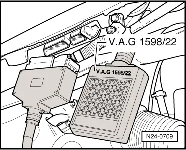
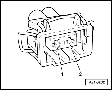
–  Connect multimeter -V.A.G 1526- to pressure switch contacts.
–  Start the engine and run at idling speed. Check pressure switch for continuity. Specification: ∞ Ω
–  Turn steering wheel to full lock. The pressure switch must switch to continuity.
If the specifications are not attained:
–  Renew pressure switch for power assisted steering:
If the specifications are attained:
–  Check the wiring → Anchor.
Checking wiring connections
–  Remove wiper arms and cowl panel: → Electrical system; Rep. Gr.92
 
Read measured value block 55           →
–  Connect test box -V.A.G 1598/22- to control unit wiring harness.
  N24-0709
–  Check wiring between test box and 2-pin connector for open circuit using current flow diagram. Contact 1+socket 49 Contact 2+socket 21 Wire resistance: Max. 1.5 Ω
–  Additionally check wires for short to one another.
–  Additionally check the wiring for short to battery positive or earth.
If no fault is detected in the pipes:
–  Renew engine control unit → Chapter.
  A24-0202

Checking matching resistor of data bus > < Checking rpm signal