
Leon Mk1
| Dismantling and assembling piston and conrod |
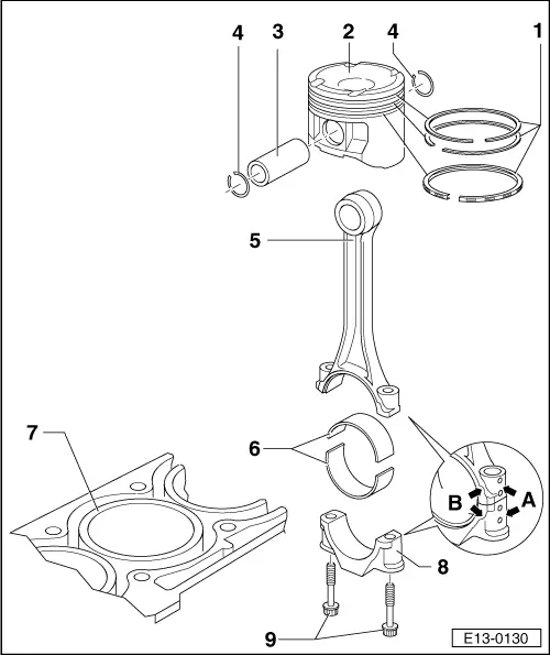
| 1 - | Piston rings |
| q | Offset gaps by 120° |
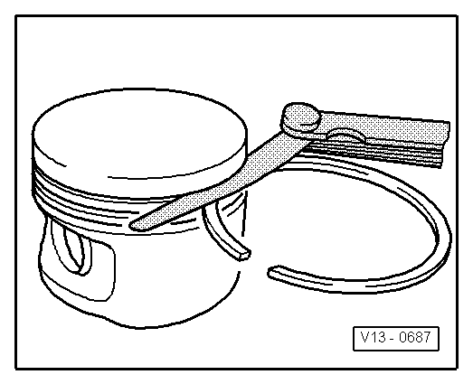
| q | Remove and install with piston ring pliers |
| q | Mark “TOP” faces towards piston crown |
| q | Checking ring gap → Fig. |
| q | Checking grove to ring clearance → Fig. |
| q | 2 or 3 part oil scraper ring, mixed installation permitted |
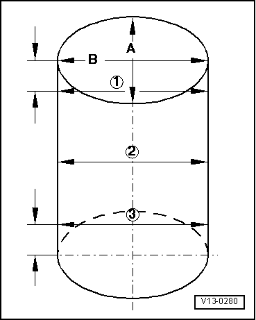
| 2 - | Piston |
| q | Checking → Fig. |
| q | Mark installation position and cylinder number |
| q | Arrow on piston crown points towards belt pulley end |
| q | Install using piston ring clamp |
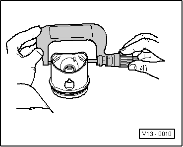
| 3 - | Piston pin |
| q | If difficult to remove, heat piston to 60 °C |
| q | Remove and install with aid of -T20019- |
| 4 - | Circlip |
| 5 - | Conrod |
| q | Renew only as a set |
| q | Mark cylinder number -A- |
| q | Installation position: Mark -B- faces towards belt pulley end |
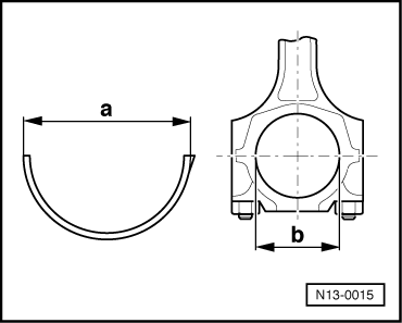
| 6 - | Bearing shell |
| q | Do not interchange used bearing shells |
| q | Measuring pre-loading → Fig. |
| q | Fit bearing shells in centralized position |
| q | Measure radial clearance with Plastigage: New: 0,006…0,047 mm Wear limit: 0.091 mm Do not rotate crankshaft when checking radial clearance |
| 7 - | Cylinder block |
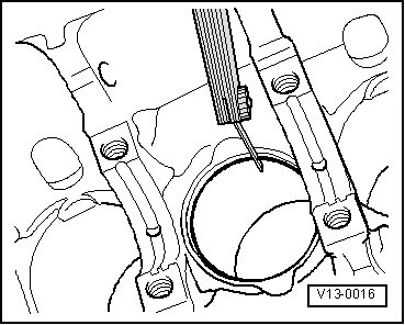
| q | Checking cylinder bore → Fig. |
| q | Piston and cylinder dimensions → Chapter |
| 8 - | Conrod cap |
| q | The caps only fit in one position on the respective conrod, this is due to the breaking procedure (cracking) separating the cap from the conrod |
| 9 - | Conrod bolt |
| q | 30 Nm + 1/4 turn (90°) further |
| q | Renew |
| q | Oil thread and contact surfaces |
| q | Tighten to a torque of 30 Nm but do not turn further when measuring radial clearance |
|
|
| Piston ring Dimension in mm | New | Wear limit |
| 1st compression ring | 0,35…0,50 | 1,0 |
| 2nd compression ring | 0,20…0,40 | 1,0 |
| Oil scraper ring | 0,25…0,75 | --- → Note |
|
|
|
| Piston ring Dimension in mm | New | Wear limit |
| 1st compression ring | 0,04…0,075 | 0,15 |
| 2nd compression ring | 0,02…0,05 | 0,15 |
| Oil scraper ring | not measurable | |
|
|
 Note!
Note!
|
|
|
|
| Bearing shell dimension -a- | |
| - | Diameter of conrod -b- |
| = | Pre-loading |
|