seat Workshop Repair Guides

SEAT Workshop Service and Repair Manuals

Removing and positioning the engine > < Technical data
Engine support: Installing and removing (Ibiza)
   
Engine support: Installing and removing (Ibiza)
Consult the equivalence table for tools and equipment according to applicability among Seat / VW / Audi / Skoda → Chapter.
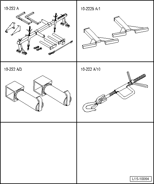
Special tools and workshop equipment required
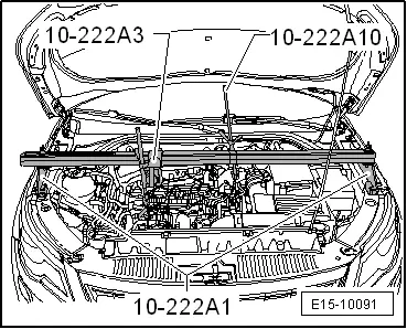
t  Socket -10 222A-, see equivalent → Anchor
t  Adapter -10 222A/1-, see equivalent → Anchor
t  Adapter -10 222A/3-, see equivalent → Anchor
t  Adapter -10 222A/10-, see equivalent → Anchor

   
Removal:
–  Loosen the engine cover at the locations -arrows- and remove.
–  Remove the vacuum line between the vacuum pump and the servo brake.
  E10-10087
–  Remove the vacuum line -arrow 1- from the bracket on the cylinder head.
Pre-heater line -arrow 2- is not necessarily installed.
–  Hang out the protective element made of foam on both front wings using the lever -80 200-.
  N15-10539
–  Pull electrical connector -2- from pressure differential sender -G505-.
–  Unclip pressure differential sender -G505--1- from lower part of fuel filter.
–  Lay pressure differential sender -G505- with lines down to rear.
  Note
Ignore -item 3-.
  N26-10525
–  Use a finger to release locking lug of fuel pre-heater valve.
–  Remove the fuel preheating valve upwards from the guide of the coolant expansion reservoir.
  N20-10638
–  Remove bolts -arrows-.
–  Separate the electrical connection -1- of the switch for coolant shortage indicator -F66- and press the coolant expansion tank to the side.
  A19-11174
–  Remove the fuel return line and the fuel supply line at the transfer location of the fuel → Chapter.
–  Catch any escaping fuel.
  N20-10436
–  Remove the filter element from the bottom part of the fuel filter.
–  Pull the insert out to the top.
–  Take the filter cartridge and the fuel hose together with the fuel preheating valve and put them on the engine.
  N20-10636
–  Fit the mount -10 222A- with the necessary adapters and attach as shown in the figure, and retain the motor in its fitting position.
  E15-10091
–  Unscrew the nut -1- and expose the earth cable.
–  Unscrew the bolts -arrows- of the engine mounting of the engine assembly.
  A10-11338
–  Thread off the screws -arrows- and remove the engine bracket with engine mounting.
  WARNING
Danger of accident
Do not loosen nut -1- unless renewing engine mounting.
Installation
Installation is carried out in reverse order, noting the following:
  Caution
The tightening sequence and specified torques for the engine bracket securing bolts must always be followed. Otherwise the engine mount may be exposed to tensioning that will result in the engine mount breaking.
l  Tightening torques → Chapter
  Note
Renew the bolts tightened with specified tightening angle.
  A10-11344
–  Mount the engine bearing on the sill.
l  The positioning boreholes -arrows- must correspond; if necessary, this must be checked using a respective drill.
  A10-11232
–  Screw in all screws -arrows- until the limit (by hand first).
–  Fully tighten bolts.
  Note
Ignore -item 1-.
  A10-11344
–  Screw in the screws -arrows- for support arm of the engine mount (by hand first) until the stop.
l  The support arm must not rotate when tightening.
–  Fully tighten bolts.
  Note
Ignore -item 1-.
Further assembly is performed in the reverse order of removal. Note the following:
t  Ensure that fuel hose connections are tight.
t  Do not interchange supply and return hose (return hose blue or blue markings, supply hose black).
  A10-11338

Removing and positioning the engine > < Technical data