seat Workshop Repair Guides

SEAT Workshop Service and Repair Manuals

Valve control > < Removing and positioning the engine
Installation
Installation
l  Tightening torques → Chapter
  Note
t  Always renew cylinder head bolts.
t  In cases of repair, carefully remove gasket remains from cylinder head and cylinder block. Ensure that no long scores or scratches are made on the surfaces. When using abrasive paper do not use a grade less than 100.
t  Carefully remove emery and abrasive remains.
t  Do not remove new cylinder head gasket from packaging until it is ready to be fitted.
t  Handle gasket very carefully. Damaging the silicone layer or the indented area will lead to leaks.
t  Exercise extreme caution. Ask a second mechanic for assistance.
t  Guide the cylinder head in the timing belt guard.
   
t  When doing this, the cylinder head must not scrape over the dowel sleeves.
–  When assembling the cylinder head, remove the counterhold -T10050- and turn the crankshaft in the opposite direction to the engine rotation until all the pistons are more or less uniform below TDC.
  N15-10530
–  Unbolt Hall sender -G40--arrow-.
  A23-0257
–  Note cylinder head gasket identification:
1 - Part number
2 - Holes
3 - Disregard
–  Fit cylinder head gasket with marking facing upwards.
  A15-10508
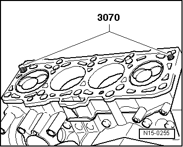
–  To centre, screw guide pins -3070/9- into outer holes on inlet side.
  Note
t  
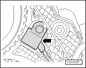
Altea - Altea XL - Leon: When assembling the cylinder head, the tensioning roller must rest on the studs.
t  Ibiza: After assembling the cylinder head, the tensioning roller must rest on the studs.
t  Ibiza: Support the engine again
t  
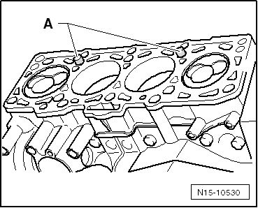
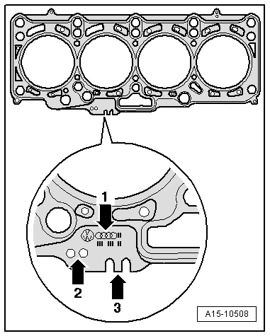
If the cylinder head gasket or cylinder head have been replaced, select the new cylinder head gasket according to the number of holes on the old cylinder head gasket.
t  If parts of the crankshaft drive have been renewed, the new cylinder head gasket must be selected by measuring the piston projection at „TDC“ → Chapter.
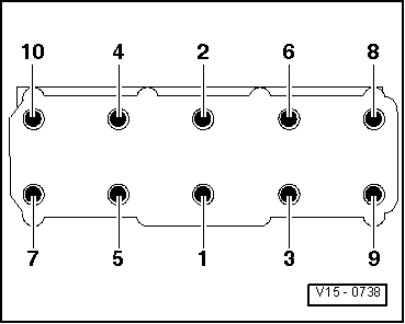
–  Fit the cylinder head, insert the 8 studs and tighten by hand.
–  Screw out the guide bolts -3070- above the bolt borehole using the screwdriver of the guide bolt -3070- and insert the cylinder head bolts.
  N15-0255
–  Tighten cylinder head in 4 stages in sequence shown as follows:
1 - Tighten initially with torque wrench:
Stage I = 35 Nm
Stage II = 60 Nm
2 - Turn further with rigid spanner:
Stage III = + 1/4 turn (90º)
Stage IV = + 1/4 turn (90º)
  V15-0738
–  Screw the Hall sender -G40--arrow- back in.
  A23-0257
Altea - Altea XL - Leon
–  Secure rear toothed belt guard -arrow- on cylinder head.
Ibiza
–  Secure rear toothed belt guard -arrow- on cylinder head after supporting it.
All vehicles (continued):
–  Install hub and camshaft pulley.
  N15-10499
–  Lock the camshaft and high-pressure pump with Diesel injection pump locking pin -3359-.
  Note
Disregard -arrows-.
  A15-10798
–  Lock the high pressure pump using the diesel injection pump locking pin -3359-.
  Note
Ignore -item 1-.
  A13-10615
–  Then turn the crankshaft in the direction of the engine rotation TDC and lock using the crankshaft stop -T10050-.
Remaining assembly is performed in reverse sequence. Note the following:
Ibiza
Support engine again → Chapter.
–  Install toothed belt → Chapter.
–  Install engine mountings → Chapter.
Altea - Altea XL - Leon
–  Install toothed belt → Chapter.
All other vehicles continued
–  Cylinder head cover: Installing → Chapter.
–  Install oil supply line and turbocharger support → Chapter.
–  Install poly V-belt → Chapter.
–  Fill up with coolant → Chapter.
–  Top up engine oil → Chapter.
After any work on the fuel system
Connect the → Vehicle diagnostic tester.
Perform the function „Bleeding fuel system“ in „guided functions“ → Chapter.
–  Carry out road test and read fault memories → Vehicle diagnostic tester.
  N15-0446

Valve control > < Removing and positioning the engine