seat Workshop Repair Guides

SEAT Workshop Service and Repair Manuals

Engine control unit (Ibiza) > < Overview of fuel preparation, injection
Removing and installing air filter housing
t  Removing → Anchor
t  Installing → Anchor
Consult the equivalence table for tools and equipment according to applicability among Seat / VW / Audi / Skoda → Chapter.
Special tools and workshop equipment required
   
t  Pliers for spring-loaded band-type clamps -VAS 6499-, see equivalent → Anchor
  W00-10700
Removing
–  Loosen the engine cover at the locations -arrows- and remove.
  E10-10087
–  Disengage the locking connection -arrows- and remove the air pipe -1-.
  A23-10553
–  Separate the plug connection on the charge pressure control solenoid valve -N75--2-.
–  Unscrew the bolt -1-.
–  Remove all vacuum lines together with their brackets -arrows- upwards from the air filter.
–  Place charge pressure control solenoid valve -N75- with vacuum hoses on engine.
  A10-11346
–  Unplug connector -3- from air mass meter -G70-.
–  Remove the air intake hose, and release the hose clip -2-.
–  Version for cold climate zones: Remove air hose; loosen hose clip -1- for this.
–  Unscrew the bolt -4- and remove the air filter housing.
Remove suction hose
  Note
As it is difficult to gain access to clip on suction hose, it is better to remove intake connecting pipe from turbocharger.
  A23-10381
–  Remove crankcase breather hose -3-.
–  Pull vacuum hose -2- off suction hose -1- and make accessible. Unclip bracket.
–  Completely undo bolt -4- (make sure bolt is captive).
–  Swivel intake connecting pipe to the right and remove together with suction hose -1-.
Install suction hose
Install in reverse order of removal; note the following:
  S23-0249
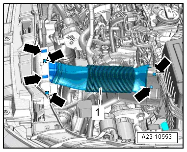
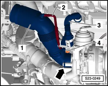
–  When mounting intake connecting pipe on turbocharger, it must be ensured that intake connecting pipe is correctly seated on the bolt of the turbocharger. -arrow-.
Installing
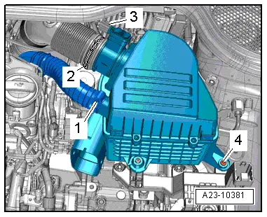
Installation is carried out in reverse order, noting the following:
  Note
t  If the air filter element is very dirty or wet, dirt or water could reach the air mass meter -G70- and affect the air mass value. This would lead to loss of power, since a smaller injection quantity is calculated.
t  In order to avoid functional problems, you should cover the critical air-conducting components such as air mass meter, air pipes etc. with a clean cloth when blowing out the air filter housing with compressed air.
t  Hose connections and air pipes and hoses must be free from oil and grease before fitting.
t  Use a silicone-free lubricant when installing the air hoses.
t  Secure all hose connections with the correct type of hose clips (same as original equipment) → Electronic parts catalogue.
–  Check suction hose (engine intake side) for salt residue, dirt and leaves and, if necessary, clean.
–  Check air duct leading from lock carrier to air filter housing for dirt and leaves. Clean if necessary.
Remaining assembly is performed in reverse sequence.
  S23-0249
–  Guide water drainage pipe -arrow- between gearbox and body.
  N23-10298
–  Check if the water drain has been mounted correctly by a visual check under the wing.
  N23-10299

Engine control unit (Ibiza) > < Overview of fuel preparation, injection