
Leon Mk1
| Overview of fitting locations |
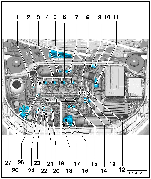
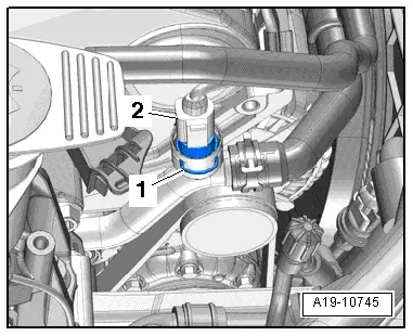
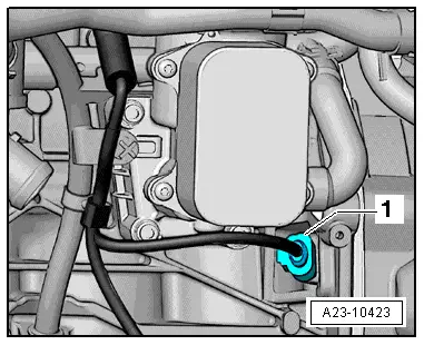
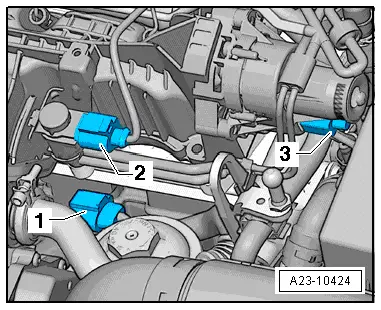
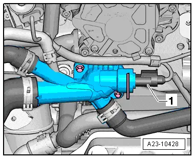
| 1 - | Differential pressure sender -G505- |
| q | Location → Fig. |
| q | Adaption must be performed after renewing this component |
| q | removing and fitting → Chapter |
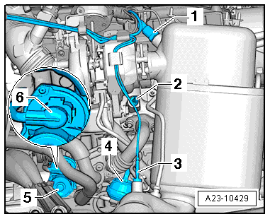
| 2 - | Hall sender -G40- (camshaft position sensor) |
| q | Location → Fig. |
| q | removing and fitting → Chapter |
| q | 10 Nm |
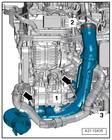
| 3 - | Exhaust gas temperature sender 3 -G495- |
| q | Location → Fig. |
| q | removing and fitting → Chapter |
| 4 - | Lambda probe -G39- withheater for the lambda probe -Z19- |
| q | Location → Fig. |
| q | removing and fitting → Chapter |
| q | 50 Nm |
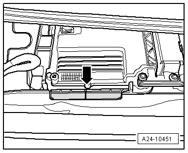
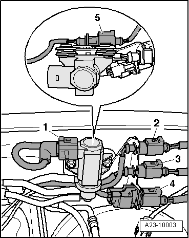
| 5 - | Engine control unit -J623- |
| q | Location → Fig. |
| q | removing and fitting → Chapter |
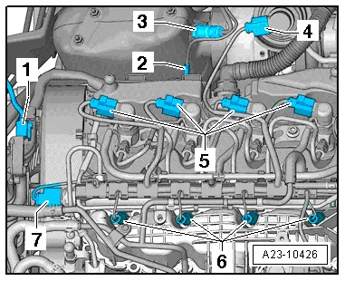
| 6 - | Injectors (piezo injectors) |
| q | Location → Fig. |
| q | removing and fitting → Chapter |
| 7 - | Position sender for charge pressure positioner -G581- |
| q | Location → Fig. |
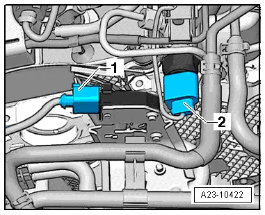
| 8 - | Fuel pressure regulating valve -N276- |
| q | Location → Fig. |
| q | removing and fitting → Chapter |
| q | 80 Nm |
| 9 - | Charge pressure control solenoid valve -N75- |
| q | Installation location, right side → Fig. |
| 10 - | Electrical connectors |
| q | Installation location, right side → Fig. |
| 11 - | Air mass meter -G70- |
| q | removing and fitting → Chapter |
| 12 - | Coolant temperature sender -G62- |
| q | Location → Fig. |
| q | removing and fitting → Chapter |
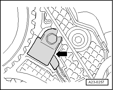
| 13 - | Engine speed sender -G28- |
| q | removing and fitting → Chapter |
| q | Location → Fig. |
| q | 4.5 Nm |
| 14 - | Intake manifold flap motor -V157- |
| q | With Intake manifold flap potentiometer -G336- |
| q | Location → Fig. |
| 15 - | Exhaust gas recirculation cooler changeover valve -N345- |
| q | Location → Fig. |
| 16 - | Pump for exhaust gas recirculation cooler -V400- |
| q | Installation location Pump for exhaust gas recirculation cooler -V400- → Fig. |
| 17 - | Throttle valve control mechanism -J338- |
| q | With throttle valve potentiometer -G69- |
| q | Location → Fig. |
| q | Intake manifold and accessory parts: Exploded view → Chapter |
| q | removing and fitting → Chapter |
| 18 - | Charge air pressure sender -G31- |
| q | Combined with intake air temperature sender -G42- |
| q | Location → Fig. |
| q | removing and fitting → Chapter |
| 19 - | Glow plugs |
| q | Location → Fig. |
| q | Glow plug 1 -Q10- |
| q | Glow plug 2 -Q11- |
| q | Glow plug 3 -Q12- |
| q | Glow plug 4 -Q13- |
| q | removing and fitting → Chapter |
| 20 - | Connection for fuel supply pipe from the fuel filter |
| q | Location → Fig. |
| 21 - | Connection for the fuel return line to the fuel filter |
| q | Location → Fig. |
| 22 - | High-pressure fuel pump with fuel metering valve -N290- |
| q | Location → Fig. |
| q | Do not open fuel metering valve -N290- |
| q | After renewing, first fuel filling „MUST“ be performed (it is important not to allow pump to run while it is still empty) → Chapter |
| q | removing and fitting → Chapter |
| 23 - | Fuel supply pipe connection (high-pressure pipe) to the fuel distributor |
| q | Location → Fig. |
| 24 - | Fuel temperature sender -G81- in the fuel supply line |
| q | Location → Fig. |
| 25 - | Radiator outlet coolant temperature sender -G83- |
| q | Location → Fig. |
| q | removing and fitting → Chapter |
| 26 - | Fuel pressure sender -G247- |
| q | Location → Fig. |
| q | removing and fitting → Chapter |
| q | 100 Nm |
| 27 - | Fuel filter: |
| q | Fuel filter - Components overview → Chapter |
| q | Removing and installing fuel filter → Chapter. |
|
|
|
|
|
|
|
|
|
|
|
|
|
|
|
|
|
|
|
|
|
|
|
|
|