seat Workshop Repair Guides

SEAT Leon Workshop Service and Auto Repair Manuals

Detaching engine from gearbox > < Removing and positioning the engine
Engine: dismounting
   
Engine: dismounting
Consult the equivalence table for tools and equipment according to applicability among Seat / VW / Audi / Skoda → Chapter.
Special tools and workshop equipment required
t  Hydraulic jack -SAT 1040-, see equivalent → Anchor
t  counterhold -T10038-, see equivalent → Anchor
t  counterhold -T20205-, see equivalent → Anchor
t  Engine sealing plug set -VAS 6122-, see equivalent → Anchor
t  Collecting tray -VAS 6208-, see equivalent → Anchor
t  Pliers for spring-loaded band-type clamps -VAS 6499-, see equivalent → Anchor
t  Stepladder

   
t  Transport lock -T10403-, see equivalent → Anchor
  W00-10761
t  
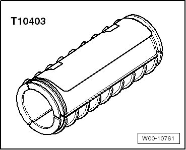
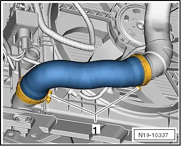
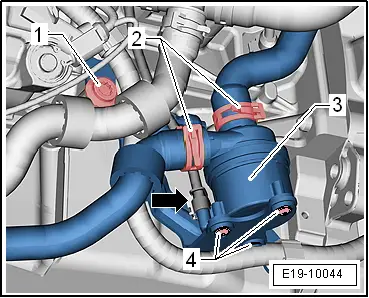
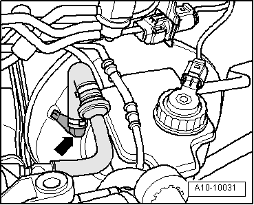
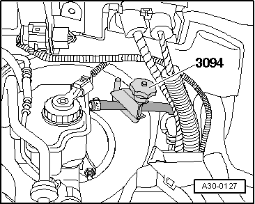
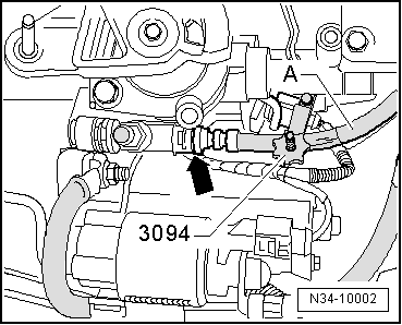
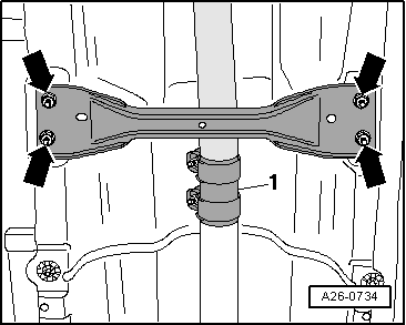
Hose clamp -3094-, see equivalent → Anchor
  Note
t  Before carrying out further work, disconnect battery earth strap. Check whether a coded radio is fitted. Where necessary, check the anti-theft coding first.
t  
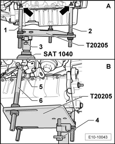
The engine is removed from underneath together with the gearbox.
t  So that the steering wheel is not locked, keep the key in the ignition.
t  The front wheels should be removed before proceeding with the removal of the engine assembly. In this way, the vehicle may be lowered using the platform until the protection plates for the disk brakes are almost touching the ground. Thus, the most ergonomic working position is achieved for reaching the components in the engine compartment.
t  
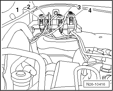
All cable ties which are opened or cut through when engine is removed must be replaced in the same position when engine is installed.
t  
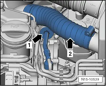
Collect drained coolant in a clean container for re-use or disposal.
t  Some components can not be removed, or only with a great deal of difficulty, while the engine is mounted. All of the faulty or damaged components should be determined before removal and should be replaced before re-installing the engine → Vehicle diagnostic, testing and information system VAS 5051.
  WARNING
When doing any repair work, especially in the engine compartment, pay attention to the following due to the cramped conditions:
t  
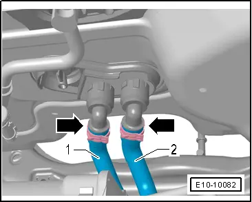
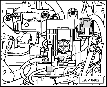
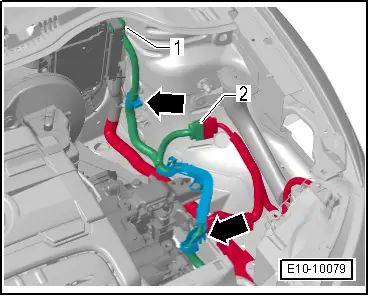
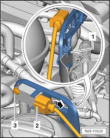
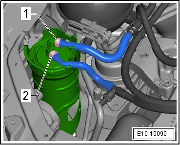
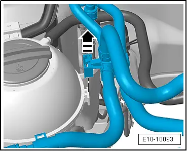
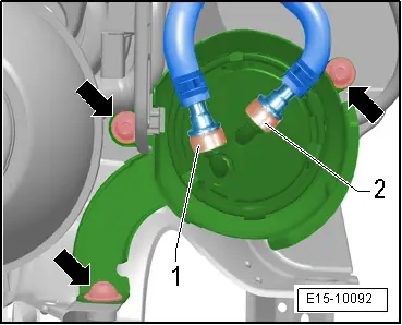
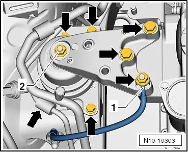
Route all the various lines (e.g. for fuel, hydraulics, active carbon filter system, coolant, refrigerant, brake fluid and vacuum pipes and hoses) and electrical wiring so that the original positions are restored.
t  
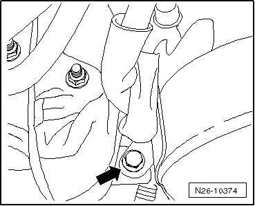
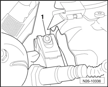
Ensure that there is sufficient clearance to all moving or hot components.
  W00-0079
Operation process
–  Loosen the engine cover at the locations -arrows- and remove.
  WARNING
Observe safety precautions when disconnecting the battery → Electrical system; Rep. gr.27.
–  With ignition switched off, disconnect earth connection from battery. → Electrical system; Rep. gr.27
  E10-10087
–  Remove the vacuum line -1- from the vacuum pump -2-.
  Note
Ignore the -arrows-.
  N15-10448
–  Loosen the spring-type clip -1- and remove the intake hose.
–  Unplug the connector -3- at the solenoid valve for charge pressure control -N75-.
–  Unscrew the nut -2- of the charge pressure control solenoid valve -N75-.
–  Remove all vacuum lines together with the brackets -5- upwards from the air filter.
–  Unplug connector -6- from air mass meter -G70-.
–  Remove the bolt -4- from the lower part of the air filter.
  E10-10091
–  Unscrew the fixing screws -arrows- of the air intake unit -1-and remove the connecting hose -2- to the air filter.
–  Remove the air filter housing together with intake line completely.
  N21-10252
–  Remove the hose -1- from the vent on the crankshaft case. Press in to release the retaining clips.
  Note
Disregard items -arrows- and item -2-.
  A21-10487
–  Loosen the angle clip -A- and remove the intake hose.
  Note
The item -arrow- can be disregarded.
  WARNING
Hot vapour/hot coolant may escape when opening expansion tank. Cover cap with cloth and open carefully.
–  Open cap on coolant expansion tank.
  N10-10285
–  Remove the front wheels.
–  Unscrew the securing bolts -arrows- and remove the engine soundproofing..
  E10-0086
–  Unscrew the -fixing elements 1 ... 3- of the right and left soundproofing.
  A10-1643
–  Remove the connecting hose »hot side« to the charge air pipe. To do this, loosen hose clip -1-.
  Note
t  Cove the charged air cooler and the hose with a clean cloth to prevent water entering.
t  After removing coolant or fuel lines, these must be sealed using the engine sealing plug set -VAS 6122- to prevent dirt from entering or coolant or fuel from running out.
–  Place the drip tray -VAS 6208- under the engine.
  N19-10337
–  Loosen the spring-type hose clip -arrow- and remove the bottom hose from the radiator.
  N19-10340
–  Unplug electrical connection -1- from the radiator fan -V7-.
  Note
Disregard item -2- .
  N19-10240
–  Loosen the spring-type hose -2- and disconnect the hoses from the coolant circulation pump 2 -V178--3-.
–  Loosen the connectors -arrow-.
–  Unscrew the bolt -1- and remove the coolant circulation pump 2 -V178- with the attached bracket.
  Note
Disregard item -4- .
  E19-10044
–  Loosen the angled bracket -arrow- and remove the right hose from the charged air cooler.
  N19-10342
–  Loosen the spring-type hose clips -arrows- and remove the top hoses from the radiator.
  E10-10078
–  Loosen the spring-type hose clips -arrow- and remove the coolant hoses to the heat exchanger of the heater.
  E10-10082
–  Remove the vacuum line between the vacuum pump and the servo brake -arrow-.
  A10-10031
–  For this purpose, remove the vacuum line -arrow 1- from the bracket on the cylinder head.
The pre-heating line -arrow 2- is not fitted in all vehicles (depending on the version).
  N15-10539
–  Unlock the retaining tabs -arrows- and remove the cover -1- upwards.
–  Loosen the retaining tabs and remove the cover of the fuse box -2- upwards.
  E97-10400
–  Unscrew the nuts -5- from the line of the fuse holder bracket and move the lines to one side.
  Note
Disregard items -1-, -2-, -3- and -4-.
  E97-10401
–  Unlock the connector -1-.
–  Unscrew the nuts -2-, -3- and -4- for securing the lines.
  Note
The nut -2- holds the line of the positive terminal of the battery in the luggage compartment..
  E97-10402
–  Release and separate the connector -1- of the engine control unit -J623- → Chapter.
–  Disconnect the connector -2- and hang out the clamping bracket of the power harness -arrow-.
–  Leave the cable harness on the power unit.
  E10-10079
–  Remove the lock washers -1- and -2- from the gearshift and selection control cable.
–  Remove the securing elements for the control cables from the selection and relay rods.
  A34-0620
–  Loosen the counter holder of the gearshift and selection control cable from the gearbox housing. For this purpose, unscrew the bolt -arrow- and move the counter holder to one side.
  A34-0621
–  Vehicles with plastic line between the pump and the clutch slave cylinder: disconnect the supply hose to the brake fluid reservoir using the hose clamp -3094-.
  A30-0127
–  Vehicles with pipe and hose line between the pump and the clutch slave cylinder: disconnect the hose hose -A- on the pipe / hose unit using the hose clamp -3094-.
  Note
Ignore -arrow-.
  Note
  N34-10002
When performing the following operations, care must be taken not to spill brake fluid onto the starter or the gearbox. If fluid comes into contact with them, the affected area must be thoroughly cleaned.
–  Pull out clip -arrow- up until the stop.
–  Remove the plastic pipe or the pipe and hose line unit -A- from slave cylinder.
  Note
Disregard: -Item B-.
–  To prevent dirt from entering, seal off open lines and connections with clean plugs from the engine sealing plug set -VAS 6122-.
  A34-10522
–  Remove the coolant hoses -1- and -4- of the expansion tank.
–  Disconnect fuel supply pipe -3- and fuel return pipe -2-, pressing on the release tabs for this purpose.
  E10-10080
–  Disconnect electrical connector -2- at pressure differential sender -G505-.
–  Remove bolt -3- from pressure differential sender -G505- bracket.
–  Place the pressure differential sender -G505- on the engine with wires connected.
  N26-10525
–  Disconnect the line from the fuel filter -1- and -2-, press the release tabs for this purpose.
–  Catch any fuel coming out.
  E10-10090
–  Remove the fuel line with attached bracket upwards from the guide of the coolant expansion reservoir.
  E10-10093
–  Remove the cartridge of the fuel filter upwards from the bottom part.
–  Unscrew the bolts -arrows-, and remove the bottom part of the fuel filter.
  E15-10092
–  Remove nut -1- for earth wire.
  Note
Disregard items -2- and -arrows-.
  N10-10303
–  Separate the connector -1- of the temperature sender after the particle filter -G527-.
–  Detach the connector -2- of the exhaust gas temperature sender 1 -G235-.
–  Disconnect electrical connection -3- for lambda probe -G39-.
–  Unplug connector -4- for the exhaust gas temperature sender 3 -G495- and move all electrical wires to the side.
  N26-10416
–  Unscrew the bolt -arrow- from the middle support of the particle filter mount.
  N26-10374
–  Separate the air temperature line of the particle filter and loosen the clip -1- between the particle filter and the exhaust gas turbocharger.
  Note
t  Disregard -item 1, 3-.
  N26-10336
t  If necessary, the hose clip -2- between the particle filter and the exhaust gas turbocharger must also be removed from above.
  A26-10721
–  Loosen the connectors -arrow-.
–  Undo the nut -1- and remove the hose -2- from the generator.
–  Set aside the wiring harness.
  E13-0199
–  Unscrew the bolts -arrows- in the engine by approx. 2 turns .
  E10-0091
–  Unscrew the bolts -arrows- in the gearbox mounting by approx. 2 turns .
–  Bring lock carrier into service position: → General body repairs, exterior; Rep. gr.50
  E10-0088
–  Unscrew the nuts on the double clamp -1-.
  Note
The position -arrows- can be disregarded.
  Note
The mounting of the front exhaust gas pipe with particle filter/catalysator should not be bent more than 10°, as otherwise it can become damaged.
–  Remove the front exhaust section from the tunnel bridge .
  A26-0734
–  Unscrew the screws -1- and the nuts -2- of the bottom support for the particle filter.
  Note
Be careful not to damage the electrical connections and cable routing.
–  Partially remove the front part of the exhaust tube with particulate filter and position it over the steering box.
Vehicles with air conditioner
–  Remove the Poly-V belt with the idler roller → Chapter
–  Remove the Poly-V belt with the tension element → Chapter
  Caution
If the Poly-V belt runs in the opposite direction when it is refitted, this can cause it to rupture.
Before removing, mark direction of operation of poly V-belt with chalk or felt-tipped pen in preparation for re-installation.
  N26-10535
–  Unplug electrical connector -2- on air conditioner compressor regulating valve -N280-.
  WARNING
The air conditioning refrigerant circuit must not be opened.
To prevent damage to the air conditioning compressor and refrigerant pipes/hoses, ensure that the pipes and hoses are not stretched, kinked or bent.
–  Remove bolts -arrow-, detach air conditioner compressor -1- with refrigerant lines connected and tie up to front.
  A87-10479
–  Suspend the air conditioner compressor above with refrigerant hoses still connected, securing it with the securing tool -T10038- to the lock carrier plate. Take special care not to damage the system.
Continued for all vehicles
  E10-10007
–  Remove bolts -arrows-.
–  Move coolant hose -3- clear.
–  Release the hose clamp -2-.
–  Unplug electrical connector -1- at charge air pressure sender -G31-/charge air pressure sender -G42- and remove the right air intake pipe.
  A21-10435
–  Disconnect the connector -1- and unscrew the nut -2- of the line of the starter.
  Note
Disregard item -3- .
  E10-0129
–  Disconnect the connector from the oil level and temperature sender -G266-.
  A17-0215
–  Remove front noise insulation -1- for sump, loosen securing parts -arrows- for this.
  A17-10410
–  Unplug the electrical connector -arrow- of the reverse gear light switch.
–  Remove right-hand articulated shaft: → Running gear, shafts, steering; Rep. gr.40.
–  Unbolt the left drive shaft from the gearbox flange.
  A34-0666
–  Joint the driveshaft to the sill -arrow-.
  A10-1680
–  Unscrew the bolts -1- and -2- of the pendulum support and remove them.
  Note
To avoid damage, take care that no current or liquids are connected.
  E34-0314
–  Bring the securing tool -T20205- with the hydraulic jack -SAT 1040- and turn the bolt -4- until it is parallel with the engine block.
–  From the rear of the engine -A-, first insert the fixed column -1-, then adjust the mobile column -2- as necessary and then screw on the nuts -arrows-.
–  From the front of the engine -B-, position the mobile column -6- and adjust the bolt -5-.
–  Adjust the bolt -3- to immobilise the securing tool -T20205-.
  Note
To remove securing bolts use a ladder.
  E10-10043
–  Unscrew the screws -arrows- from the top right from the engine assembly and gearbox.
  E10-0091
–  Unscrew the screws -arrows- from the top left from the engine assembly and gearbox.
  Caution
Danger of damage to hoses, pipes and wiring connections and to engine compartment.
t  Check that all hoses and wiring connections between engine, gearbox, subframe and body have been detached.
t  Carefully guide the engine assembly until it is removed from the engine compartment.
–  Carefully lower the engine and gearbox.
–  Pull engine/gearbox assembly as far as possible forwards and lower it slowly downwards.
  Note
Engine and gearbox must be guided carefully when lowering to prevent damage to the bodywork.
  Caution
When it looks like the engine should remain removed for a longer period, align the lines of the air conditioning system tension free.
  E10-0088

Detaching engine from gearbox > < Removing and positioning the engine