seat Workshop Repair Guides

SEAT Workshop Service and Repair Manuals

Engine assembly mountings > < Attaching engine to repair stand
Engine: fitting
Engine: fitting
Operation process
   
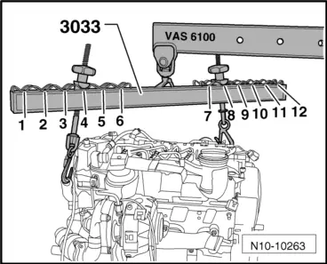
–  Hook the support tool -3033- on the engine and on the workshop crane -VAS 6100-, as shown in the figure.
Flywheel side: item 4.
Vibration damper side: item 8.
Installation is carried out in the reverse order of removing, when doing this note the following.
  Note
t  When fitting, replace the self-locking nuts and bolts.
t  Renew bolts which have a specified tightening angle, as well as seals and gaskets.
t  Secure all hose connections with the correct hose clips (same as original equipment) → Parts catalogue.
t  Clean input shaft splines and, for used clutch plates, hub splines; remove corrosion and apply a thin coat of grease → Parts Catalogue to the splines. Then move the clutch plate on the input shaft from side to side, until the hub moves smoothly on the shaft. Excess grease must be removed.
  N10-10263
–  Check whether dowel sleeves for centring the engine/gearbox assembly are fitted in the cylinder block; install if necessary.
–  Observe that the intermediate plate is fitted on sealing flange and is slid onto the dowel sleeves -arrows-.
–  Check the centring of the clutch drive plate → Rep. gr.30 .
–  Check clutch release bearing for wear and renew if necessary.
–  Lightly grease the clutch release collar, release collar sleeve and the input shaft teeth → Parts Catalogue.
–  Screw the gearbox to the engine.
  Note
t  Specified torques only apply to lightly greased, oiled, phosphated or blackened nuts and bolts.
t  Additional lubricant such as engine or gearbox oil may be used, but do not use graphite lubricant.
t  Use is never to be made of degreased parts.
t  Tolerance for tightening torques: ± 15 %.
  A13-0682
Engine/gearbox mountings
  A37-0214
Pos.BoltNm
t  1
t  2
1)2)
M12×5580
t  3
t  4
1)2)
M12×16580
t  5
1)2)
M12×10580
t  6
t  7
1)2)
M10×5040
t  8
1)2)
M10×7040

1) M8 thread bolt
2) Renew bolt
A - Dowel sleeves to centre
–  Mount the engine assembly / gearbox onto the support tool -T20205-.
Requirement
l  The engine assembly / gearbox is mounted onto the support tool -T20205-.
–  Insert the engine/gearbox assembly into the body.
–  When inserting the engine assembly with the counterhold -T20205- ensure that there is sufficient clearance with regard to the bodywork.
–  When fitting the engine assembly, continue with care so that the bodywork is not damaged.
   
–  Screw the bolts into the assembly mounting -B- by hand. Secure with new bolts → Chapter .
  N10-0350
–  Screw the bolts into the assembly mounting (on the gearbox side) -arrow- by hand. Secure with new bolts → Chapter .
–  Align the engine using a shaking movement so that the supports are not under any tension.
  Note
The bolts are tightened to the specified torque only after adjusting the engine mountings .
–  Remove the securing tool -T20205- from the engine.
–  Fit the complete half-shafts → Running gear, axles, steering; Rep. gr.40.
  E10-0088
–  Screw the bolts -1- and -2- of the pendulum support. Tightening torque → Anchor
  Note
Use new screws
–  Install the front exhaust section with the particle filter → Chapter.
–  Install the exhaust system and align free of stress → Chapter.
–  Install the air conditioner compressor → Heating, air conditioning; Rep. gr.87.
–  Fit coolant hoses → Chapter.
–  Install the Poly-V belt with the idler roller → Chapter
–  Install the Poly-V belt with the tension element → Chapter.
–  Electrical connections and routing → Current flow diagrams, Electrical fault finding and Fitting locations.
–  Install clutch slave cylinder → Rep. gr.30.
  WARNING
Do not press on the clutch pedal before fitting the slave cylinder.
–  Gear mechanism: attach and adjust on the gearbox → Rep. gr.34.
–  Place the lock carrier plate into service position → Bodywork, exterior fitting work; Rep. gr.50
–  Install the air hoses
–  Adjust engine mountings .
–  Install battery → Electrical system; Rep. gr.27.
–  Check oil level → Chapter.
–  Fill up coolant → Chapter.
  Note
t  The drained coolant can only be reused if the cylinder head or the cylinder block have not been replaced.
t  Contaminated or dirty coolant must not be used again.
  WARNING
Do not use a battery charger to start the engine! The control units of the vehicle may be damaged.
–  Check the headlight settings → Electrical system; Rep. gr.94.
–  Carry out road test and read fault memories → Vehicle diagnostic, testing and information system VAS 5051.
Tightening torques
  E34-0314
ComponentNm
Bolts/nutsM610
 M715
 M820
 M10:45
 M1265
discrepancies: 
Gearbox mounting to gearbox60 + 90° (1/4 turn) 1)
Left supercharger air tube to the oil sump10
Pendulum support to gearbox30 + 90° (1/4 turn) 1)
Pendulum support to subframe40 + 90° (1/4 turn) 1)
Lock carrier to the bodywork10
Terminal + to starter motor16
Earth wire to gearbox22
Front supercharger air tube to the engine block22

1) Renew bolts
   

Engine assembly mountings > < Attaching engine to repair stand