
Leon Mk1
 Note
Note
|
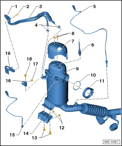
| 1 - | Differential pressure sender -G505- |
| q | removing and fitting → Chapter |
| 2 - | 3 Nm |
| 3 - | Control lines |
| 4 - | Clips |
| 5 - | Exhaust gas temperature sender 4 -G648-, 45 Nm |
| q | removing and fitting → Chapter |
| q | Thread of sender is coated. |
| q | Do not additionally oil or grease. |
| 6 - | Lambda probe -G39-, 50 Nm |
| q | removing and fitting → Chapter |
| q | Apply high-temperature lubricant -G 052 112 A3- to thread only. The high-temperature lubricant -G 052 112 A3- must not get into the slots on the probe body. |
| q | To remove use the set of flat ring spanners -3337- |
| 7 - | Heat shield |
| 8 - | 9 Nm |
| 9 - | Particulate filter |
| q | With oxidation catalytic converter and front exhaust pipe. |
| q | After renewing, the adaption of ash mass comparison must be set to zero with the vehicle diagnosis tester under „Guided functions“. |
| q | removing and fitting → Chapter |
| 10 - | Gasket |
| q | Replace |
| q | Note installation position. |
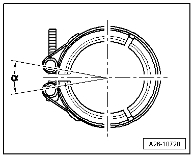
| 11 - | Clamp; 7 Nm |
| 12 - | 25 Nm |
| 13 - | 25 Nm |
| 14 - | Bracket |
| q | Bolted to cylinder head |
| q | Version with threaded pins: |
| q | Replacing particulate filter bracket with riveted stud bolt → Electronic parts catalogue. |
| q | This is the only way the required tightening torque can be applied. |
| 15 - | Exhaust gas temperature sender 3 -G495-, 45 Nm |
| q | Exhaust gas temperature sender 3 -G495-: removing and fitting → Chapter |
| q | Lubricate the thread with hot bolt paste -G 052 112 A3-. |
| 16 - | Bracket |
| 17 - | 25 Nm |
| 18 - | 45 Nm |
| q | For control line |
| 19 - | Bracket |
| q | For pressure differential sender -G505-. |
|
|
|
|
|
|